Foldable eyepiece cup

a cup and eyepiece technology, applied in the field of eyepiece cups, can solve the problems of affecting the use of eyepieces and thus of optical observation instruments, and achieve the effect of reducing the number of glasses

Active Publication Date: 2006-09-12
STEINER OPTIK
View PDF9 Cites 14 Cited by
  • Summary
  • Abstract
  • Description
  • Claims
  • Application Information

AI Technical Summary

Benefits of technology

[0015]In keeping with another embodiment of the invention, it is advantageously provided that the peripheral wall consists of flexible plastic or rubber material. These materials enable the peripheral wall to be folded down easily into a corresponding position.
[0017]Appropriately, the peripheral wall is foldable in the vicinity of the light-protecting attachment, ensuring the third stable position of ventilation. In this third position of ventilation, there is flow between the surroundings and the above-mentioned space, enabling the space to be ventilated.
[0021]A one-piece peripheral wall is of considerable advantage. It helps in manufacture at a low cost.

Problems solved by technology

As a result, the temperature within this space rises gradually while the optical observation instrument is used, resulting in the lens misting up, which considerably affects the use of the eyepiece and thus of the optical observation instrument connected thereto.

Method used


Image

  • Foldable eyepiece cup
  • Foldable eyepiece cup
  • Foldable eyepiece cup

Examples


Embodiment Construction

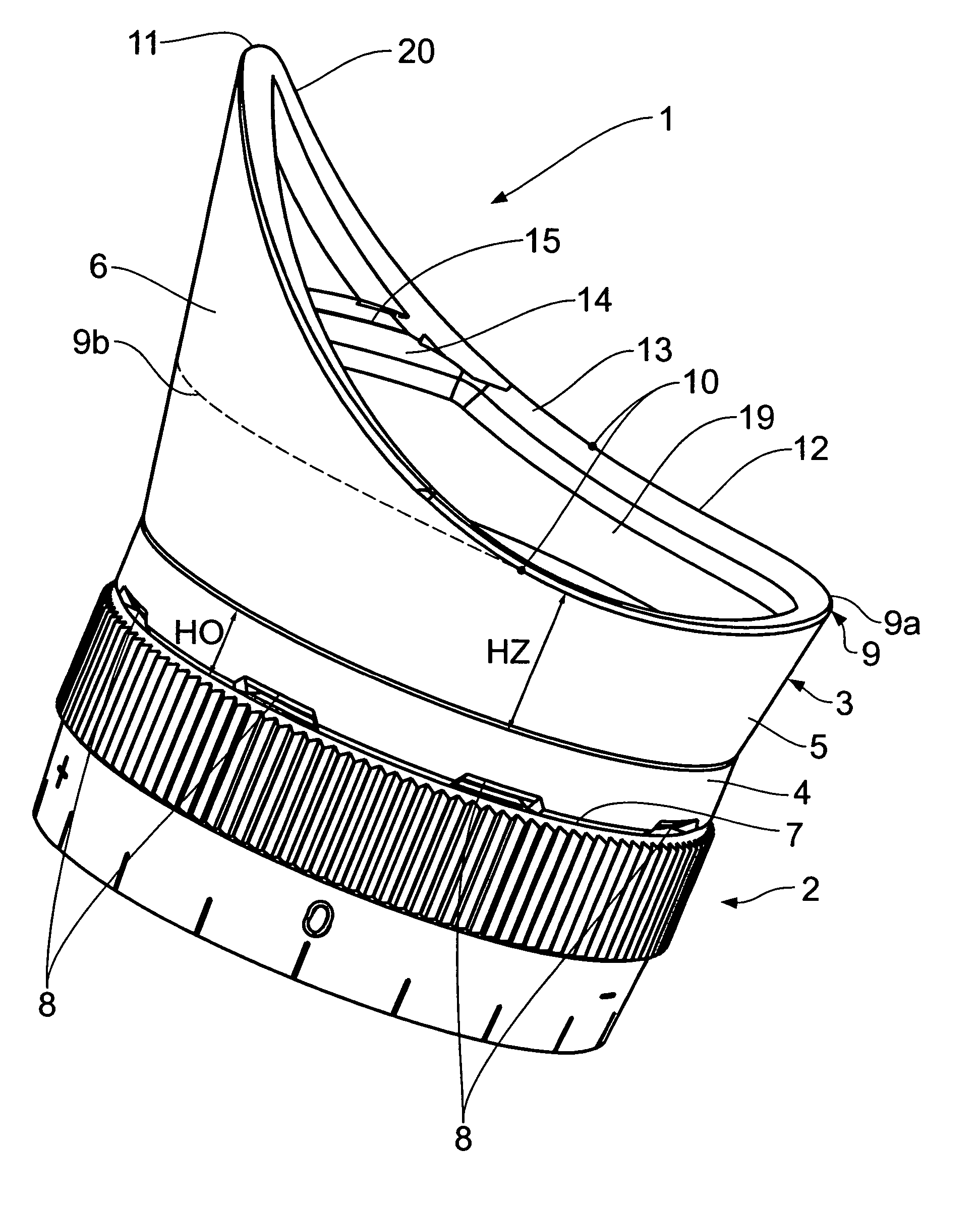
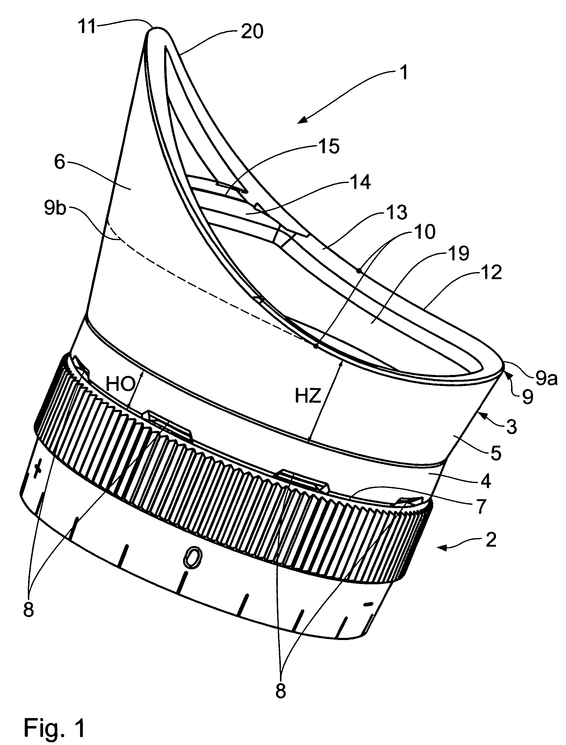
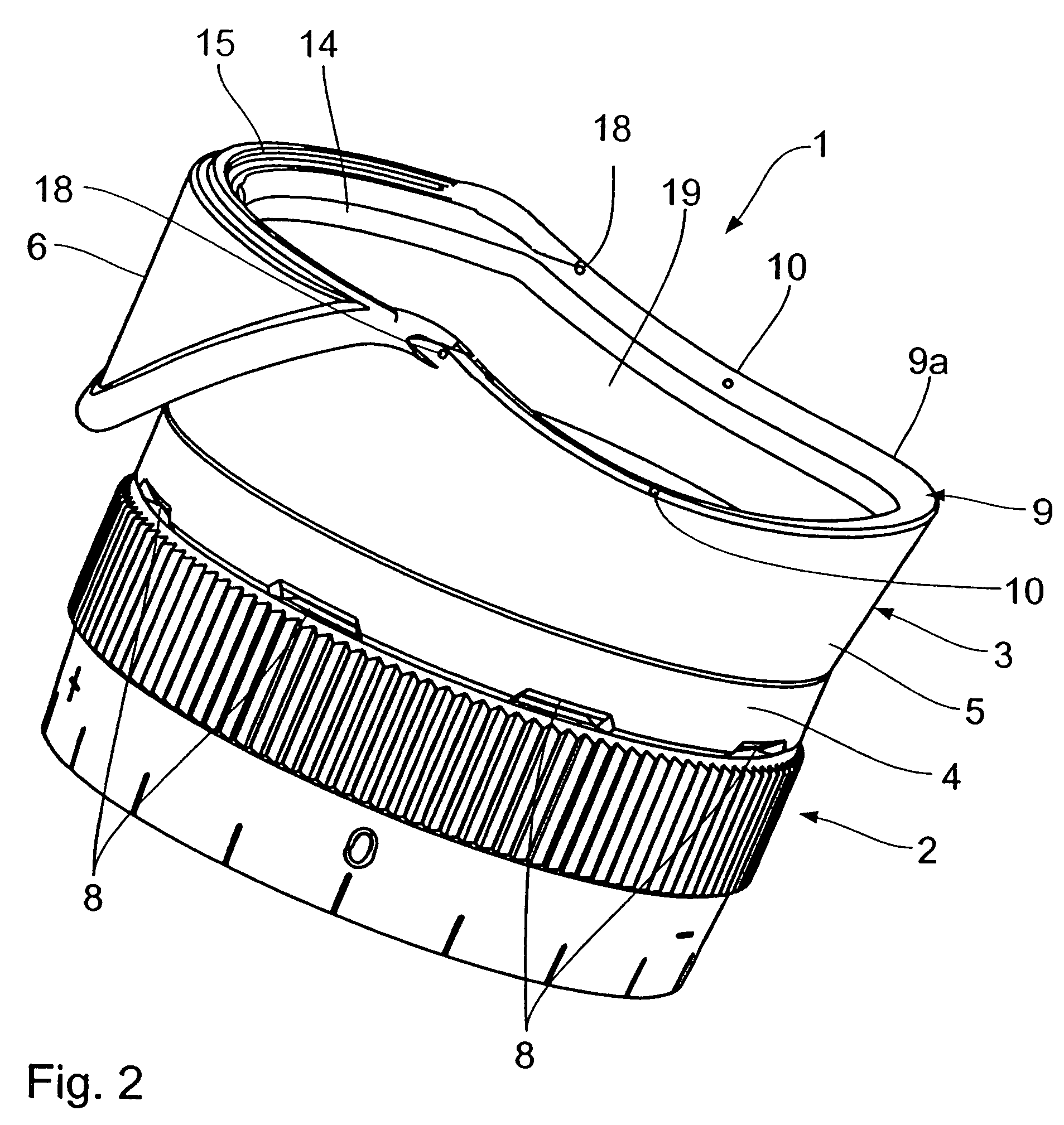
[0026]An eyepiece cup 1 seen in FIGS. 1 to 3 is mounted on an eyepiece 2 of an optical observation instrument. The optical observation instrument may be for instance a microscope, binoculars or a telescope.

[0027]The eyepiece cup 1 is comprised of a one-piece peripheral wall 3 of flexible plastic material or rubber material. The peripheral wall 3 includes an eyepiece-connecting section 4, which adjoins the eyepiece 2, for connection of the eyepiece cup 1 to the eyepiece 2; a transition section 5 which adjoins the eyepiece-connecting section 4; and a light-protecting attachment 6 which is joined to the side of the transition section 5 that faces away from the eyepiece-connecting section 4. The light-protecting attachment 6 is connected to the transition section 5 only by a part of the circumference thereof. The peripheral wall 3 laterally defines a sight hole 19 which is located above an eyepiece lens (not shown).

[0028]The eyepiece-connecting section 4 extends from a free bottom edge ...


PUM


Abstract

A cup for an eyepiece of an optical observation instrument, comprises a peripheral wall which includes an eyepiece-connecting section for connection of the cup to an eyepiece, a transition section which adjoins the eyepiece-connecting section, a light-protecting attachment which, by way of a sectional part of the transition section, is joined to a side of the transition section that is turned away from the eyepiece-connecting section; a sight hole which is laterally defined by the peripheral wall; the peripheral wall being movable into a first, non-folded end position for someone who does not wear spectacles for preclusion of any incidence of stray light upon an eyepiece lens, and into a second, folded end position for spectacle wearers; and into a third stable position of ventilation, located between the first and the second end position, for someone not wearing spectacles.

Description

BACKGROUND OF THE INVENTION[0001]1. Field of the Invention[0002]The invention relates to a cup for an eyepiece of an optical observation instrument, comprising[0003]a peripheral wall which includes[0004]an eyepiece-connecting section, connecting the cup to the eyepiece,[0005]a transition section which adjoins the eyepiece-connecting section,[0006]a light-protecting attachment which, by way of a sectional part of the transition section, is joined to a side of the transition section that is turned away from the eyepiece-connecting section;[0007]a sight hole which is laterally defined by the peripheral wall;[0008]the peripheral wall being movable[0009]into a first non-folded end position for someone who does not wear spectacles for preclusion of any incidence of stray light upon an eyepiece lens, and[0010]into a second folded end position for spectacle wearers.[0011]2. Background Art[0012]An eyepiece cup of the generic type is known for example from DD 243 126 A1. Spectacle wearers hav...

Claims


Application Information

Patent Timeline
Patent Type & Authority Patents(United States)
IPC IPC(8): G02B21/00G02B23/16G03B11/04G03B17/00G02B25/00
CPCG03B11/04G02B23/16G03B11/046
Inventor FISCHBACH, MANFREDSTEINER, CARL
Owner STEINER OPTIK
Why Eureka
Try Eureka