Rotary connector
a technology of rotary connectors and connectors, applied in the direction of current collectors, electric/fluid circuits, vehicle components, etc., can solve the problems of abnormal noise and difficulty in accurately molding parts, and achieve the effect of reducing manufacturing costs
- Summary
- Abstract
- Description
- Claims
- Application Information
AI Technical Summary
Benefits of technology
Problems solved by technology
Method used
Image
Examples
first embodiment
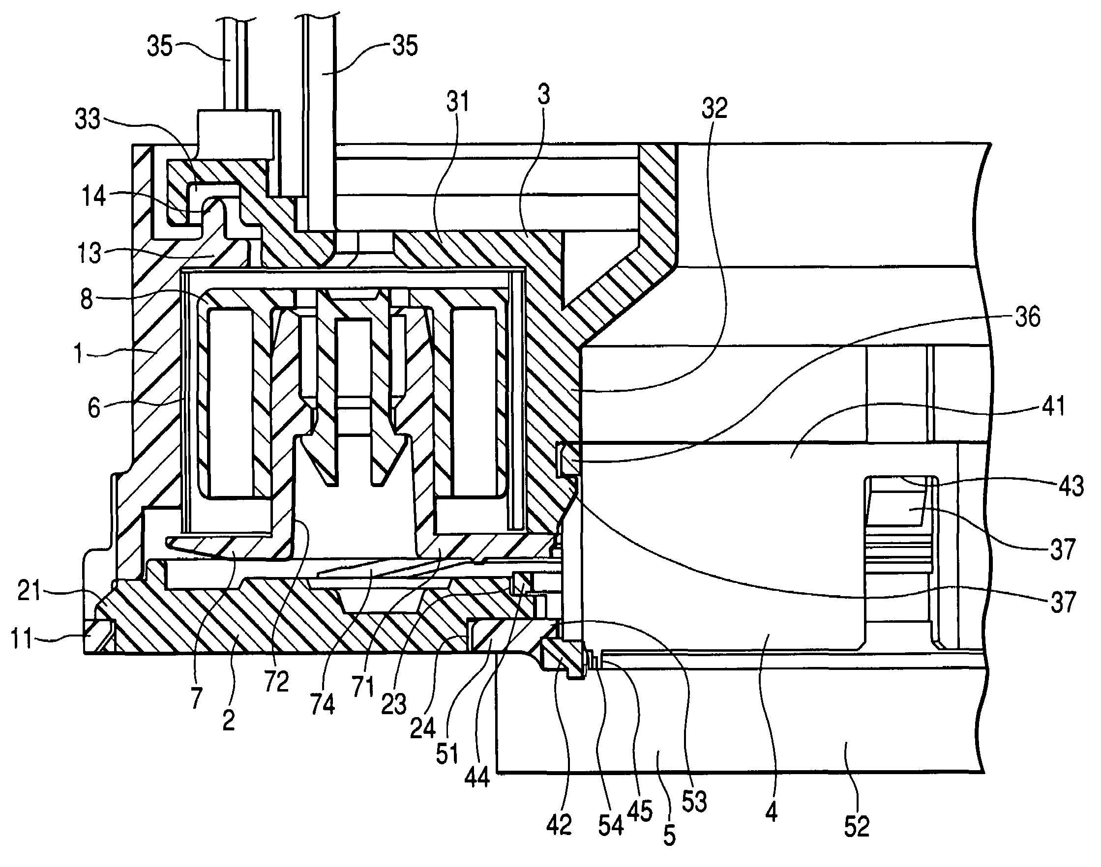
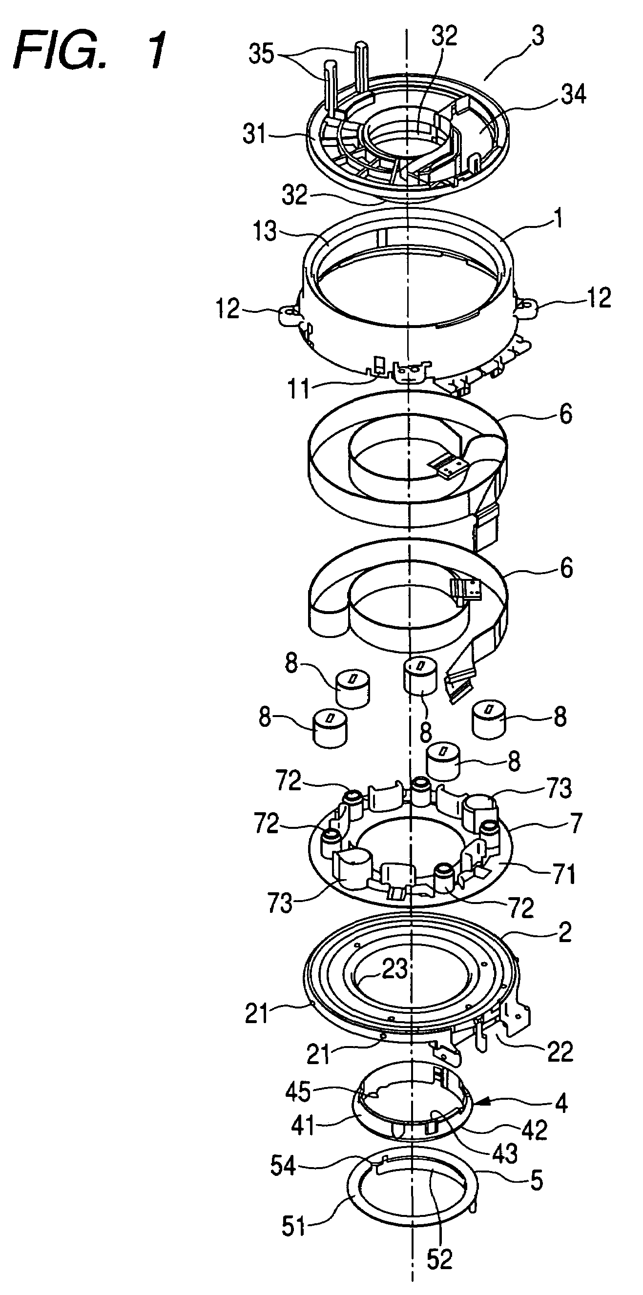
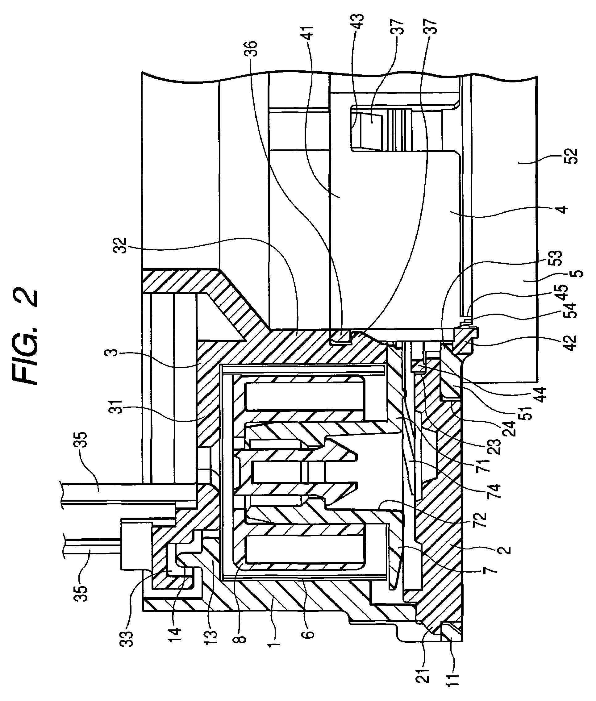
[0033]Hereinafter, a rotary connector according to the invention will be described with reference to FIGS. 1 and 2. FIG. 1 is an exploded perspective view showing a rotary connector according to the present embodiment, and FIG. 2 is a cross-sectional view showing main parts of the rotary connector according to the present embodiment.
[0034]As shown in FIG. 1, the rotary connector according to the present embodiment is mainly composed of a case 1, a cover 2, a rotor (movable-side housing) 3, a rotor snap 4, a cancel member 5, flexible cables 6, a ring-shaped holder 7, and rollers 8. Every member other than the flexible cables 6 is made of insulating resin.
[0035]The case 1 is formed in a cylindrical shape having a required size, and first engaging parts 11 for snap-fitting the cover 2 and mounting bosses 12 for fixing the case 1 to a stator part of a vehicle are formed on the lower side of an outer circumferential surface of the case 1. Furthermore, an annular protrusion 13 protrudes i...
second embodiment
[0061]In the rotary connector the inner rim of the cover 2 is interposed between the holding projection 44 and the ring-shaped plate part 51 with a small clearance, and a side surface of the ring-shaped plate part 51 faces a wall surface forming the step of an engaging step 24 with a small clearance. Therefore, it is possible to simultaneously regulate an axial position and a radial position of the movable-side housing with respect to the fixed-side housing by a portion close to a rotation axis of the rotor (movable-side housing) 3, and to accurately mold the position regulating portions with resin. Moreover it is possible to reduce deformation caused by temperature variation and variation per hour. For this reason, it is possible to suppress occurrence of abnormal noise during the rotation of the movable-side housing.
[0062]Furthermore, in the rotary connector according to the second embodiment, since the engaging step 24 is formed on the inner rim of the lower surface of the cover...
third embodiment
[0065]In the rotary connector as shown in FIG. 4, a holding step 23 capable of receiving an outer circumferential surface of holding projection 44 which is formed on a rotor snap 4 is formed on an inner rim of an upper surface of the cover 2 instead of forming an engaging step 24 on an inner rim of a lower surface of the cover 2, as shown in FIG. 3.
[0066]A wall surface forming a step of the holding step 23 is formed so as to face the side surface of the holding projection 44 formed on the rotor snap 4 with a small clearance when the cover 2 and the rotor snap 4 are assembled with each other. In addition, a wall surface forming a step of the holding step 23 is formed so that an inner rim of the cover 2 is interposed, with a small clearance, between the lower surface of the holding projection 44 formed on the rotor snap 4 and a ring-shaped plate part 51 included in the cancel member 5 when the cover 2, the rotor snap 4, and a cancel member 5 are assembled with each other.
[0067]In the...
PUM
 Abstract
Description
Claims
Application Information
 - R&D
- Intellectual Property
- Life Sciences
- Materials
- Tech Scout
- Unparalleled Data Quality
- Higher Quality Content
- 60% Fewer Hallucinations
Browse by: Latest US Patents, China's latest patents, Technical Efficacy Thesaurus, Application Domain, Technology Topic, Popular Technical Reports.
© 2025 PatSnap. All rights reserved.Legal|Privacy policy|Modern Slavery Act Transparency Statement|Sitemap|About US| Contact US: help@patsnap.com


