

Cutting guide apparatus and surgical method for use in knee arthroplasty
- Summary
- Abstract
- Description
- Claims
- Application Information
AI Technical Summary
Benefits of technology
Problems solved by technology
Method used
Image

Examples
Embodiment Construction
[0020]The present invention is directed to a novel cutting guide system and method for preparing a distal femur. For ease of explanation, the following description will be directed to the preparation of the distal femur.
[0021]As used herein, “knee arthoplasty” means total knee replacement surgery through surface preparation and soft tissue balancing to accommodate an anatomically correct resurfacing of the femur, tibia, and patellar articular surfaces.
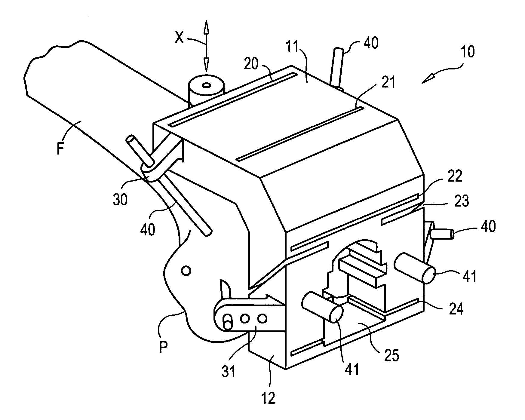
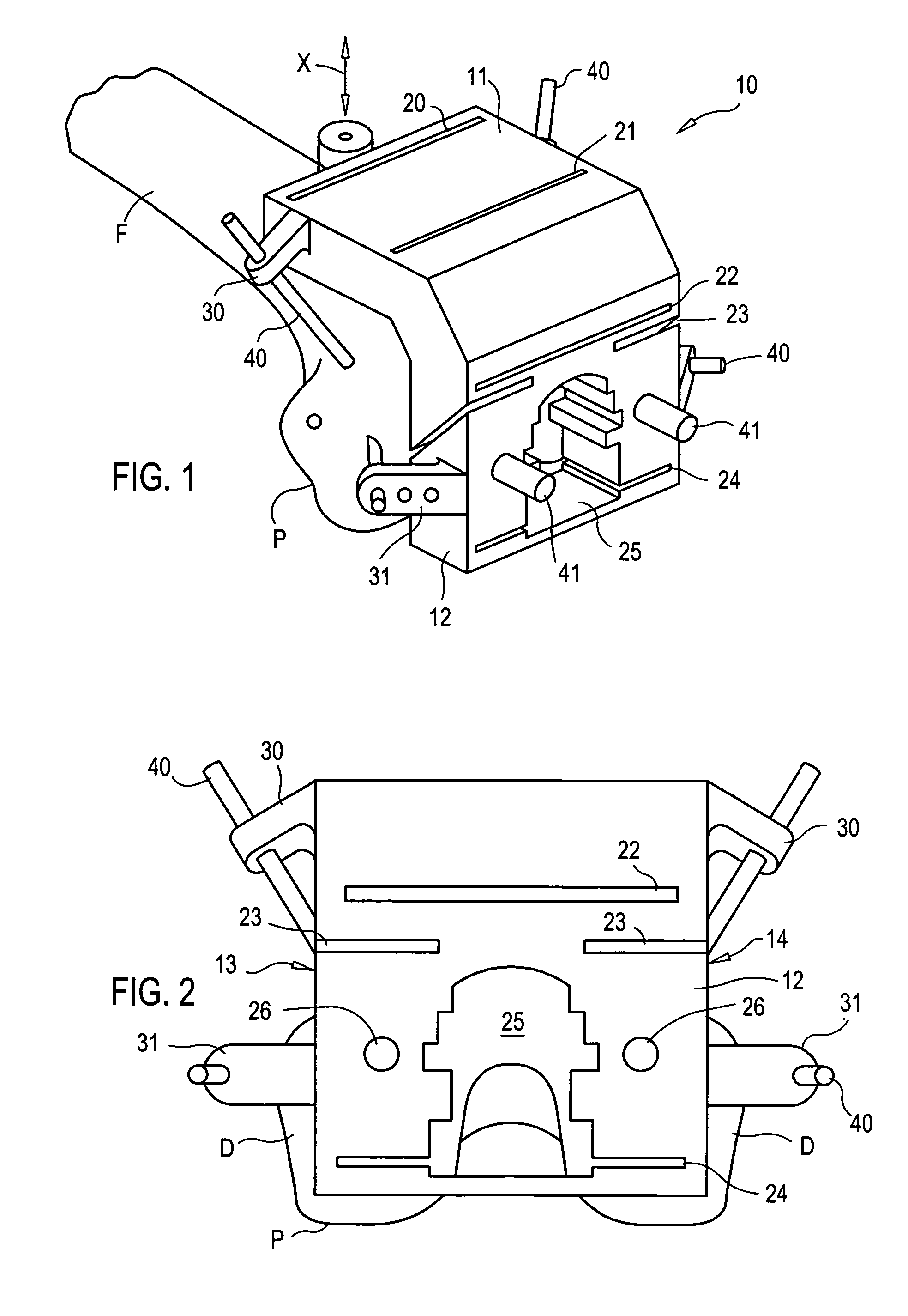
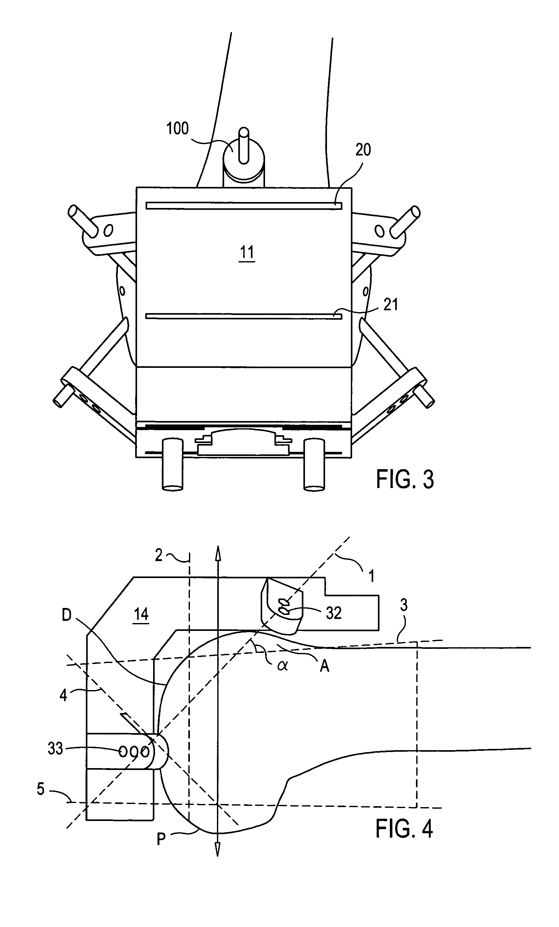
[0022]Referring now to the figures, the present invention is directed to cutting guide apparatus comprising a cutting guide block configured for alignment and attachment to the distal end of a femur.
[0023]Referring specifically to FIGS. 1–5, the cutting guide apparatus comprises cutting block 10 having an anterior portion 11 and a distal portion 12. As shown, the anterior portion 11 and distal portion 12 of the cutting block are made with reference to the corresponding anterior A and posterior P side of a femur F. The anterior portion ...
PUM
 Abstract
Description
Claims
Application Information