
Keypad assembly

a keypad and assembly technology, applied in the field of keypad assemblies, can solve the problems of confusing many users, confusing the user of the electronic device, and the encapsulation of a traditional keypad assembly has proved problemati

Inactive Publication Date: 2006-09-12
SIEMENS AG
View PDF2 Cites 139 Cited by
  • Summary
  • Abstract
  • Description
  • Claims
  • Application Information

AI Technical Summary

Benefits of technology

"The present invention is about a keypad assembly that uses touch detecting apparatus such as force sensors or touchpad assemblies for registering key presses. The keypad assembly is suitable for use in electronic devices such as mobile phones, cordless phones, calculators, or handheld computers. The invention provides a method for manufacturing encapsulated keypad assemblies and electronic devices employing an encapsulated keypad assembly. The keypad assembly includes a substrate with force sensors or electroluminescent sheets for detecting key presses. The invention allows for adjustable force registration for canceling preload forces and provides a transparent touchpad for detecting touch or force applied over a key. The encapsulation layer may comprise a portion of the housing of the electronic device. The technical effects of the invention include improved accuracy and reliability of keypad assembly and improved user experience."

Problems solved by technology

This remapping of key assignments can cause confusion for the user of the electronic device employing the keypad assembly, and is limited by the original layout of the keys of the keypad assembly.
However, in most applications, the number of keys available for use as function keys is constrained by the space allotted on the display, since use of the display for displaying functions limits the display area that may be used for other purposes.
Consequently, functions typically must be presented in a menu format, which many users find confusing.
However, encapsulation of a traditional keypad assembly has proven problematic.
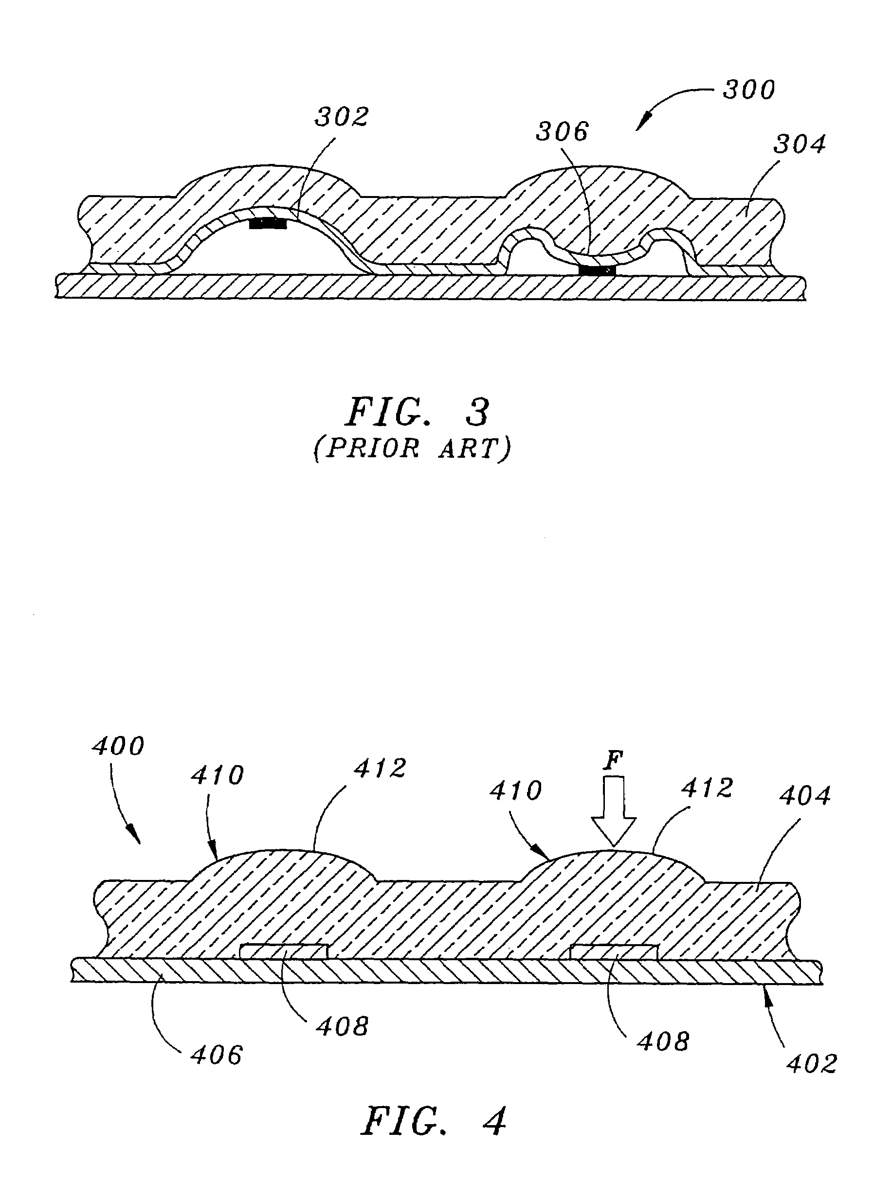
Moreover, because the keypad assembly 300 is permanently encapsulated within the housing material of the electronic device, the electronic device typically cannot be repaired and must be discarded, resulting in unacceptable manufacturing waste when encapsulation methods are used.

Method used


Image

  • Keypad assembly
  • Keypad assembly
  • Keypad assembly

Examples


Embodiment Construction

[0021]Reference will now be made in detail to the presently preferred embodiments of the invention, examples of which are illustrated in the accompanying drawings.

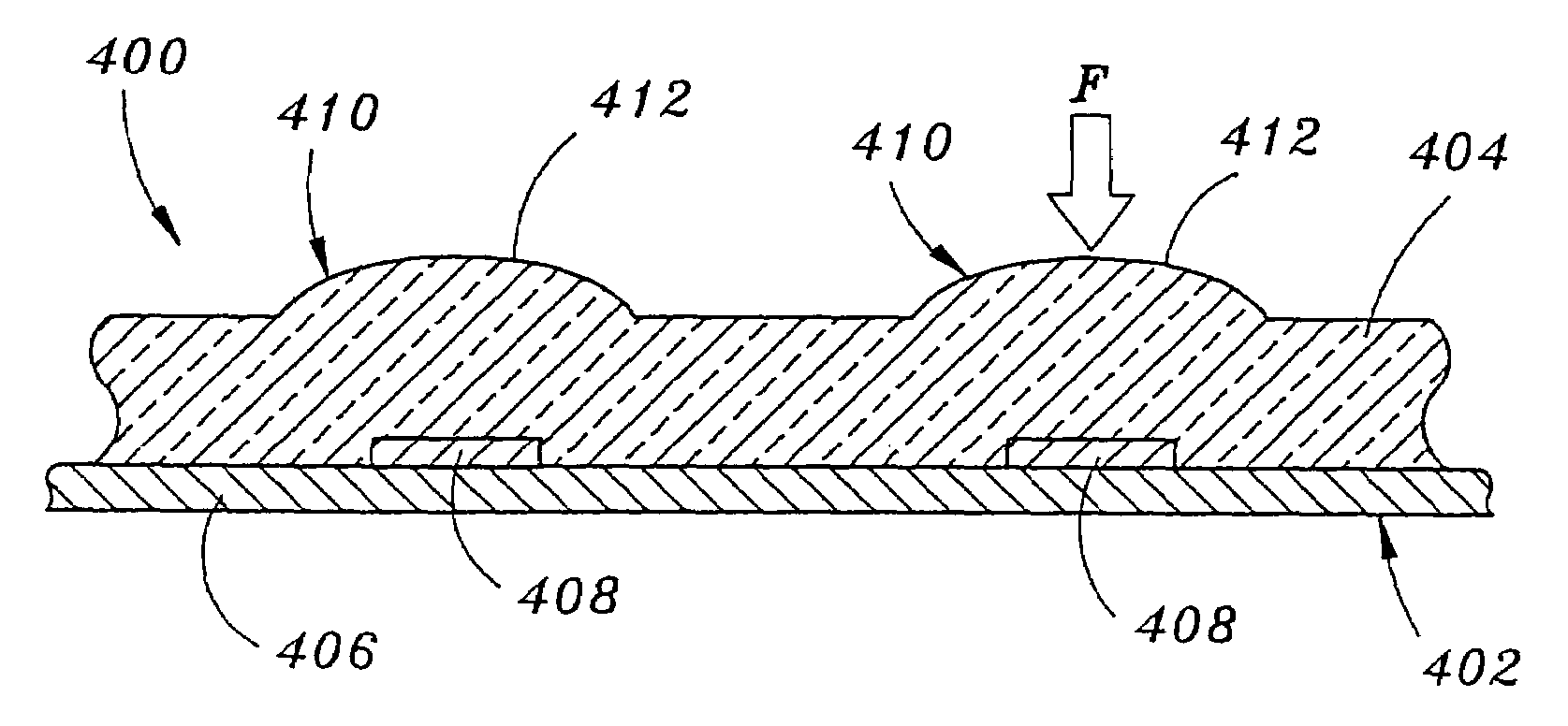
[0022]FIG. 4 illustrates an encapsulated keypad assembly 400 in accordance with an exemplary embodiment of the present invention. The keypad assembly 400 is comprised of a keypad 402 and an encapsulation layer 404 molded to, and at least partially encapsulating, the keypad 402. As shown in FIG. 4, the keypad 402 includes a substrate 406 having one or more force sensors 408 disposed thereon. In exemplary embodiments, the substrate 406 is comprised of a printed circuit board (PCB) providing circuitry for interconnecting the force sensors 408 with the processing system of the electronic device. However, it is contemplated that the substrate 406 may alternately comprise any surface suitable for supporting the force sensors 408. Thus, for example, the substrate 406 may comprise a sub-layer of a housing of an electronic device e...


PUM

PropertyMeasurementUnit
forceaaaaaaaaaa
resilientaaaaaaaaaa
shapeaaaaaaaaaa

Abstract

A keypad assembly utilizes touch-detecting apparatus such as force sensors or touchpad assemblies for registering key presses. In exemplary embodiments, the keypad assembly is suitable for use in electronic devices such as a mobile telephones, calculators, hand-held computers, or the like, having single piece molded housings wherein the keypad assembly is at least partially encapsulated within the housing.

Description

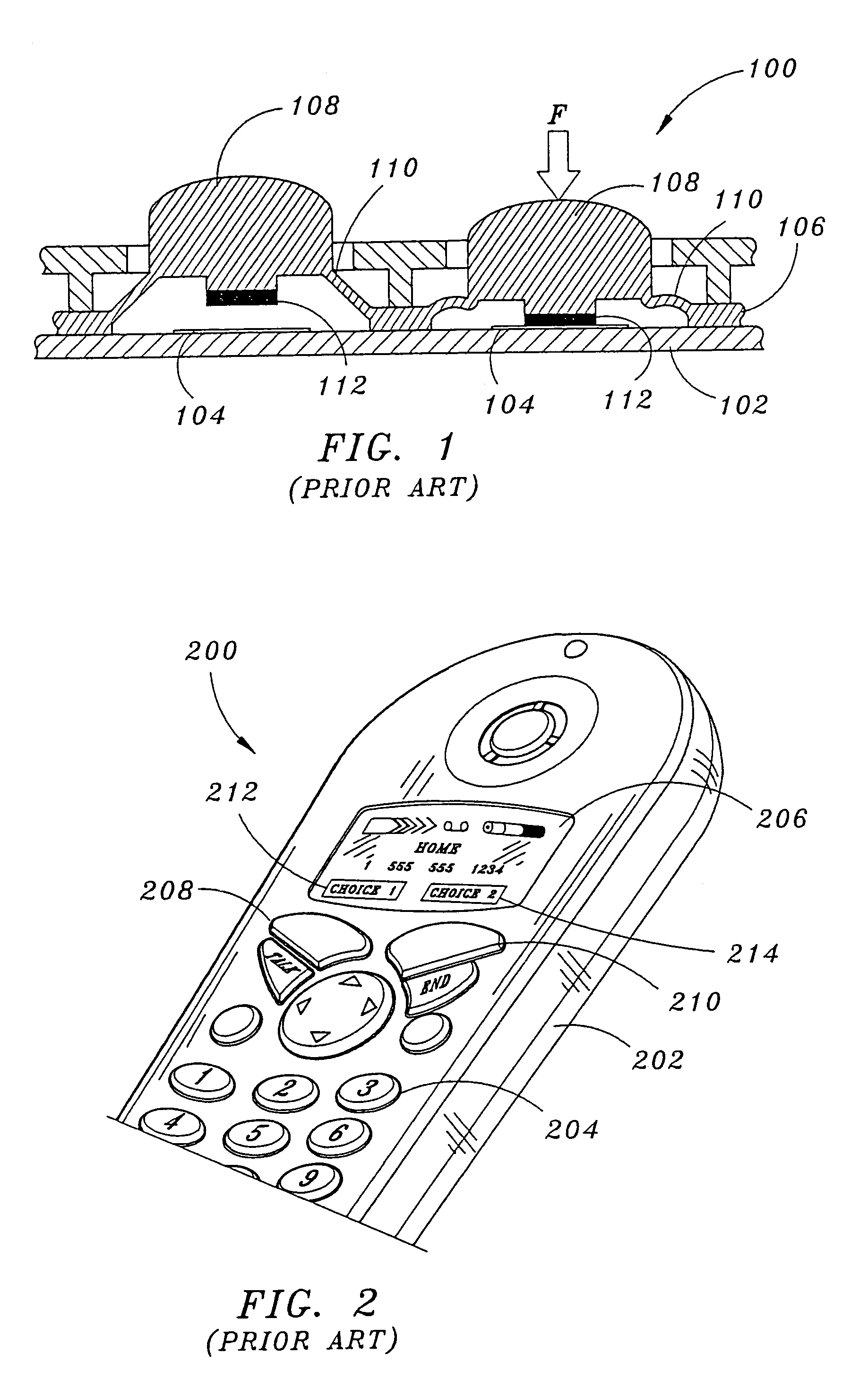
CROSS-REFERENCE TO RELATED APPLICATIONS[0001]This application is a continuation of U.S. patent application Ser. No. 10 / 247,234, filed Sep. 19, 2002 now U.S. Pat. No. 6,824,321, wherein is herein incorporated by reference in its entirety.BACKGROUND OF THE INVENTION[0002]The present invention relates generally to keypad assemblies used in electronic devices such as mobile telephones, cordless telephone handsets, hand held computers, or the like, and more particularly to keypad assemblies employing touch detecting apparatus capable of sensing forces applied to keys of the keypad assembly for registering key presses.[0003]Hand held electronic devices such as mobile telephones, cordless telephone handsets, hand-held computers, calculators, and the like, often employ keypads for entry of information and commands. FIG. 1 illustrates a traditional keypad assembly used in such devices. The keypad assembly 100 includes a circuit board 102 having a plurality of conductors 104. A keypad 106 is ...

Claims


Application Information

Patent Timeline
Patent Type & Authority Patents(United States)
IPC IPC(8): H03M11/00B29C49/00B29C51/00G06F3/02G06F3/033G06F3/048H01H13/702H04M1/23H04M1/72403H04M1/72427H04M1/7243H04M1/72445
CPCG06F3/0202G06F3/04886H01H13/702H03K17/9643H04M1/23H04M1/72522B29C49/00H04M2250/70B29L2031/3431H01H2201/02H01H2209/014H01H2209/016H01H2217/024H01H2219/02H01H2221/002H01H2221/09H01H2227/034H04M1/72544H04M1/72547H04M1/72561B29C51/00H04M1/72427H04M1/7243H04M1/72445H04M1/72403
Inventor WARD, ISAACWESELAKE, KENNETH
Owner SIEMENS AG
Learn More