

Camera control system
a control system and camera technology, applied in the field of camera control system, can solve the problems of no camera control, image of no interest cannot be picked up,
- Summary
- Abstract
- Description
- Claims
- Application Information
AI Technical Summary
Benefits of technology
Problems solved by technology
Method used
Image

Examples
first embodiment
[0031](First Embodiment)
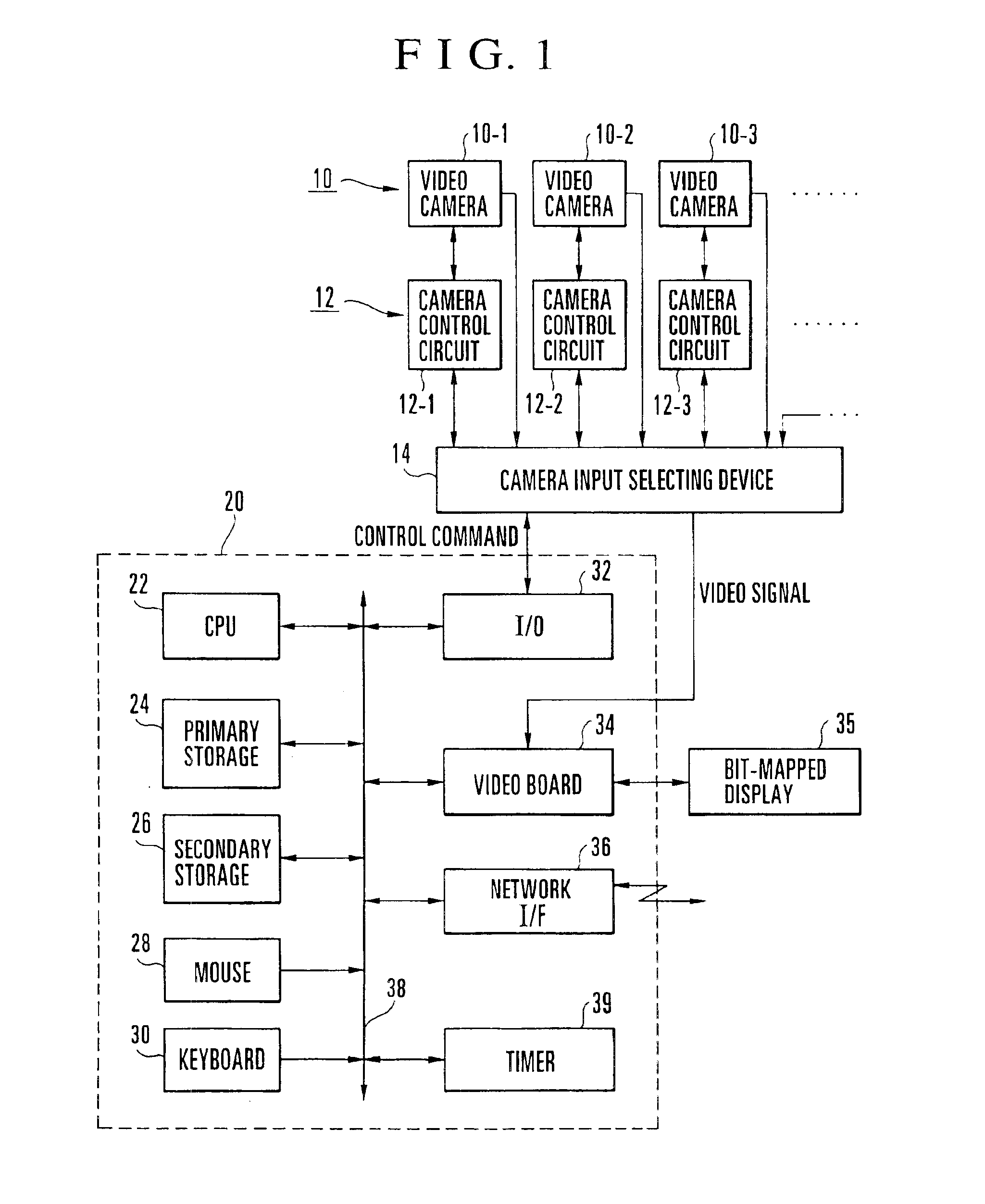
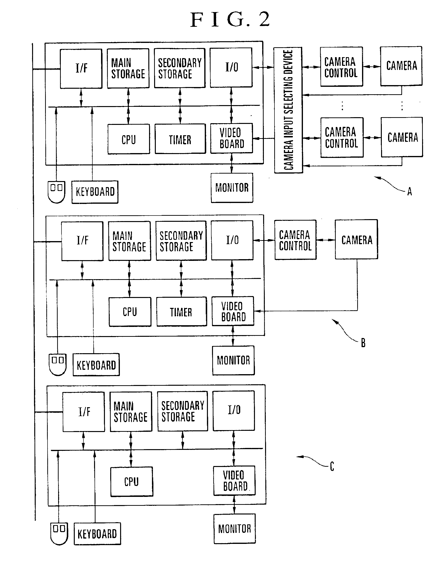
[0032]FIG. 1 is a schematic block diagram of a computer terminal to which a plurality of cameras are connected. The computer terminal shown in FIG. 1 and a plurality of computer terminals each having a construction similar to that shown in FIG. 1 are interconnected via a network to constitute the entire camera control system.
[0033]Referring to FIG. 1, reference numeral 10 generally denotes video cameras (10-1, 10-2, 10-3, . . . ) each of which can be made to adjust its operating conditions such as panning angle, tilting angle, zoom magnification, focus position and backlight correction, and reference numeral 12 generally denotes camera control circuits (12-1, 12-2, 12-3, . . . ) which control the operations of the respective video cameras (10-1, 10-2, 10-3, . . . ), such as panning, tilting, zooming, focus adjustment and iris operation, on the basis of external control signals. A camera input selecting device 14 is arranged to select from among the video came...
second embodiment
[0070](Second Embodiment)
[0071]In the second embodiment, a plurality of video cameras are connected to one camera server, and the control rights of the respective video cameras connected to the camera server are given to one camera client. The construction of the camera control system used in the second embodiment is identical to that shown in FIGS. 1 to 3, and the description thereof is omitted.
[0072]In the second embodiment, software modules, such as a module for outputting in a time-division manner the video data of the plurality of video cameras (for example, video cameras D, E and F) which are changed over by the camera input selecting device 14 or exclusive transmission modules for the respective video cameras D, E and F, are incorporated in the video transmitting / receiving software 64 of the camera manipulating device 20 so that the video data of the plurality of the video cameras D, E and F connected to the camera server 50 via the camera input selecting device 14 can be out...
third embodiment
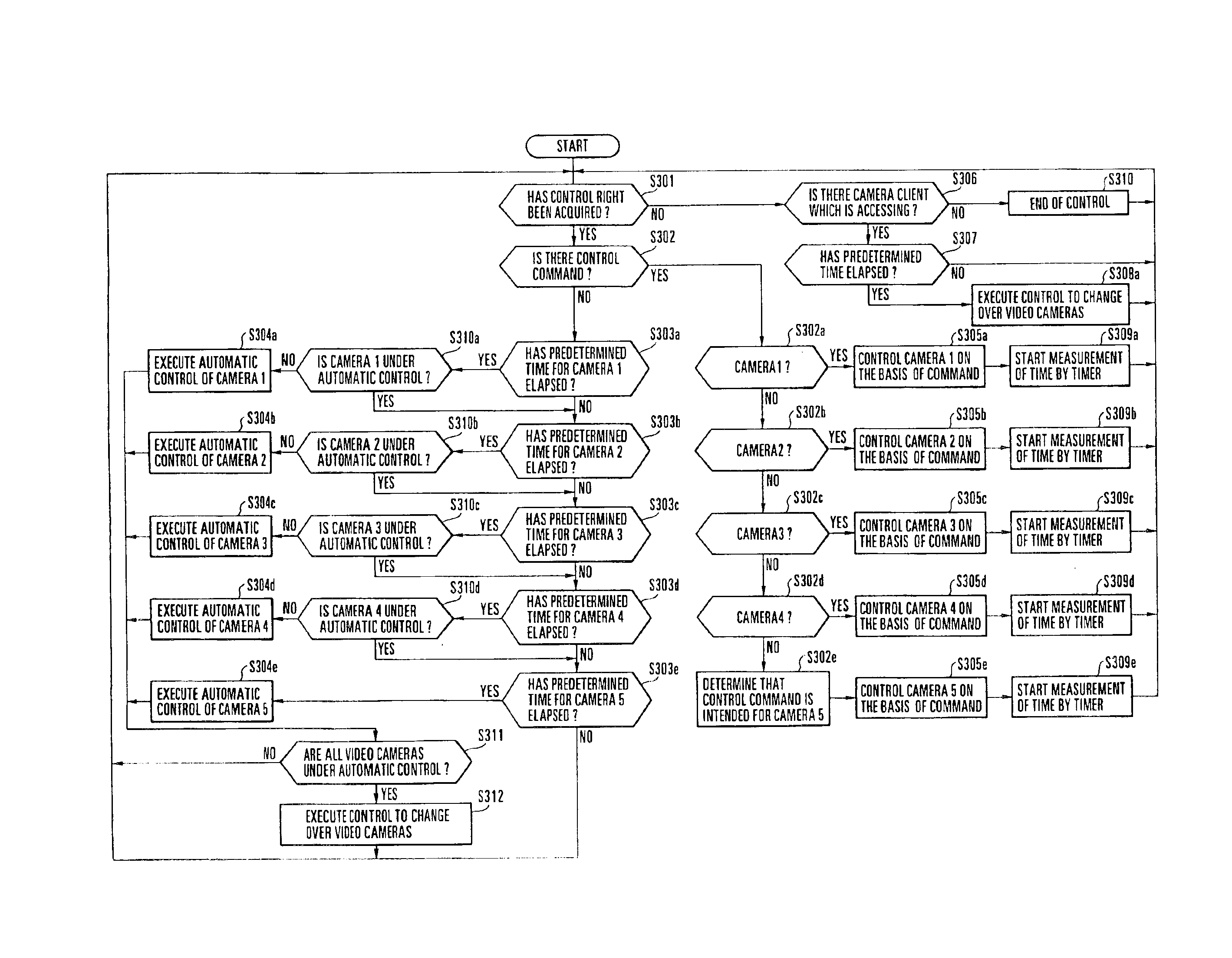
[0088](Third Embodiment)
[0089]The third embodiment makes it possible to display a video image received from a video camera on a large display window as shown in FIG. 5, in an arrangement in which a plurality of video cameras are connected to one camera server.
[0090]In the third embodiment, if the control rights of video cameras are not acquired by any camera client or if the control rights of video cameras are acquired by a camera client but a control command to control the image pickup direction or the zooming of any one of the video cameras connected to a camera server is not received for a predetermined time, automatic control of the video cameras is executed while the video cameras are being changed over from one video camera to another.
[0091]FIG. 10 shows a monitor window displayed on the side of a camera client, which is similar to that used in the second embodiment. In the third embodiment, if any one of the camera icons (in FIG. 10, CAMERA 1 to CAMERA 5) displayed on the map...
PUM
 Abstract
Description
Claims
Application Information