
Air conditioning system for vehicle

a technology for air conditioning systems and vehicles, applied in refrigeration components, transportation and packaging, light and heating equipment, etc., can solve the problems of increased temperature in the passenger compartment of the vehicle, inconvenient condition where the windows are fogged, and occupants' discomfort, so as to achieve comfortable temperature and prevent the increase in the interior temperature of the passenger compartmen

Inactive Publication Date: 2006-09-19
HONDA MOTOR CO LTD
View PDF13 Cites 16 Cited by
  • Summary
  • Abstract
  • Description
  • Claims
  • Application Information

AI Technical Summary

Benefits of technology

The invention is an air conditioning system for a vehicle that saves power and maintains a comfortable interior temperature even when the engine is stopped. It achieves this by increasing the output of a secondary compressor in advance before the primary compressor is stopped. This prevents the interior of the vehicle from getting hot or too cold. The system can also activate the primary compressor to provide an auxiliary means to the output of the secondary compressor when the secondary compressor reaches a predetermined value. This prevents the interior of the vehicle from getting hot or too cold. Overall, the system ensures that the vehicle's interior remains comfortable even when the engine is stopped.

Problems solved by technology

As a result, when the outside temperature is high or the sunlight is intense, the temperature of a passenger compartment of the vehicle increases, whereby there may occur a case where occupants feel uncomfortable.
On the contrary, when the outside temperature is low, the dehumidifying capability is lowered to be short, and breath expelled from the occupants increases the humidity inside the passenger compartment, causing an inconvenient condition where windows are fogged.

Method used


Image

  • Air conditioning system for vehicle
  • Air conditioning system for vehicle
  • Air conditioning system for vehicle

Examples


Embodiment Construction

[0024]An embodiment of an air conditioning system for a vehicle according to the invention will be described in detail below by reference to the accompanying drawings.

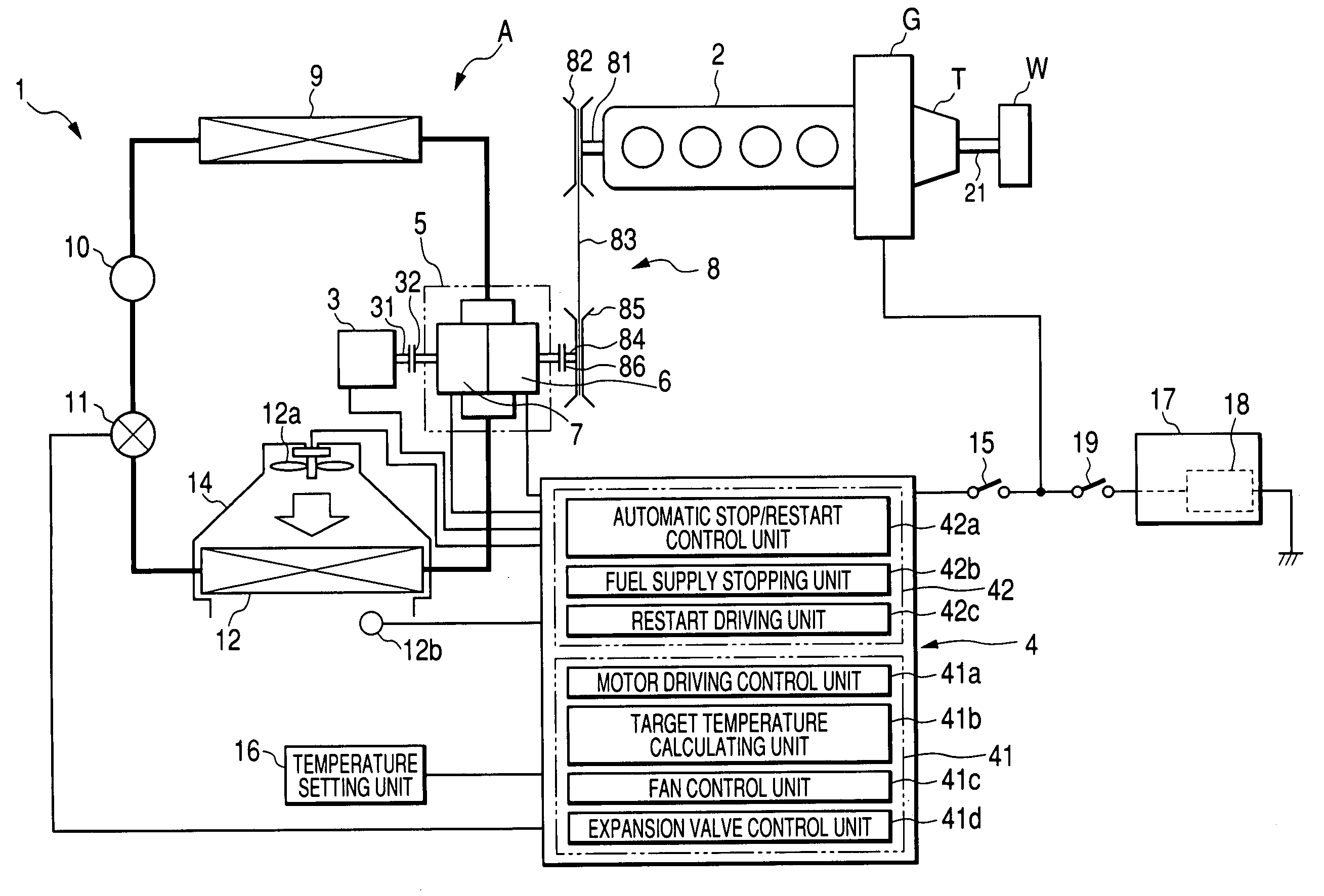
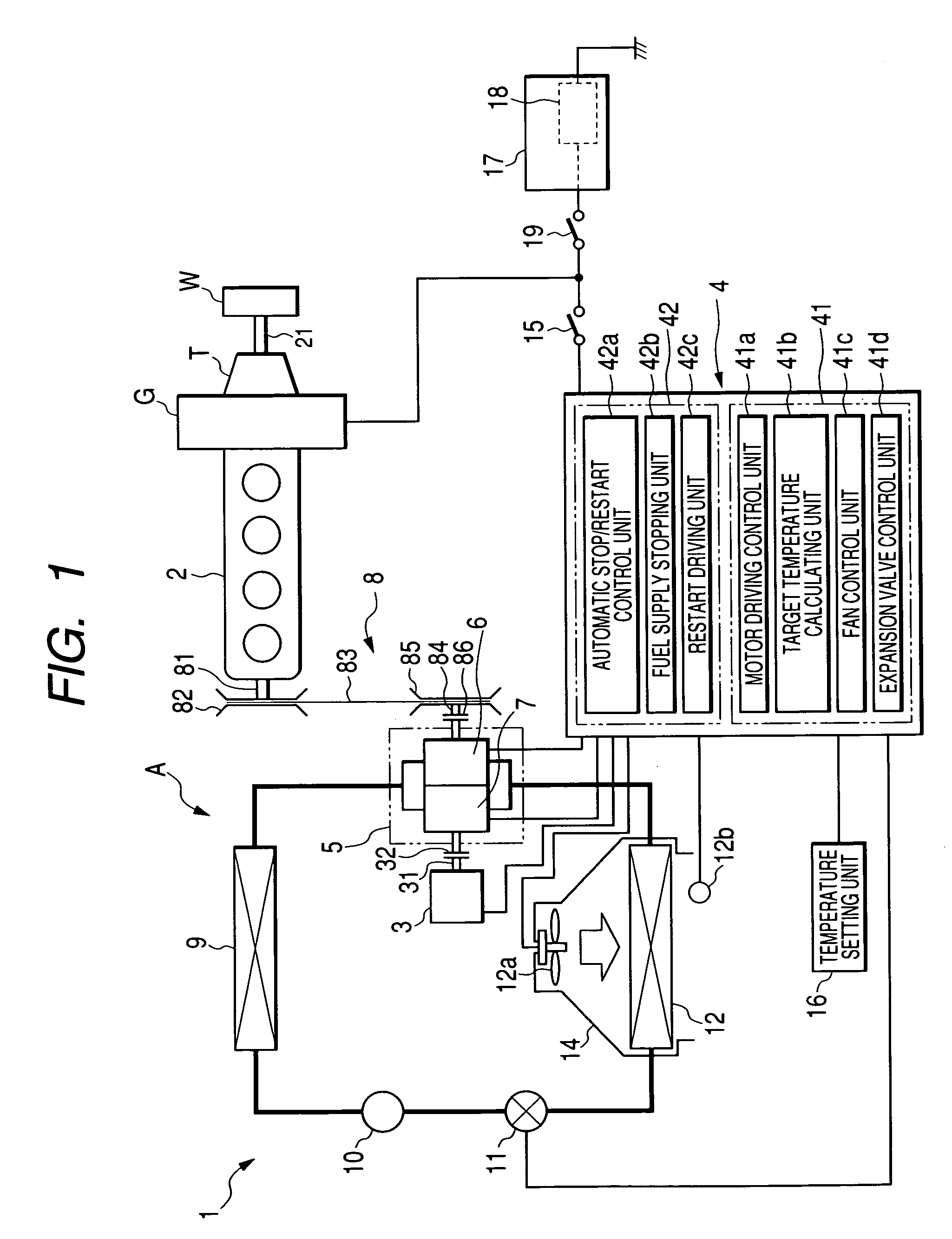
[0025]FIG. 1 is a schematic drawing showing an air conditioning system for a vehicle according to an embodiment of the invention.

[0026]As shown in FIG. 1, the air conditioning system (hereinafter, referred simply to an “air conditioning system”) is such as to operate using as driving sources an engine 2 which is a driving source of a vehicle and a motor 3 for a motor-driven compressor 7.

[0027]While the air conditioning system 1 is optimum as a system that is installed, for example, in a vehicle having a function to temporarily stop the idling of an engine thereof, the air conditioning system may be installed either in the vehicle having the stop-idling function or in a vehicle having no such stop-idling function.

[0028]Hereinafter, an embodiment of the invention will be described by taking as an example an air condition...


PUM


Abstract

An air conditioning system includes a primary or engine-driven compressor that is driven by a primary driving source or engine, and a secondary or motor-driven compressor that is driven by a secondary driving source or motor. The air conditioning system increases in advance an output of the secondary or motor-driven compressor before the primary or engine-driven compressor is stopped. Further, when a load of the secondary or motor-driven compressor becomes a predetermined value while the secondary or motor-driven compressor is in operation, the primary or engine-driven compressor is activated.

Description

BACKGROUND OF THE INVENTION[0001]The present invention relates to an air conditioning system for a vehicle including a primary compressor which is driven by a primary driving source including an engine and a secondary compressor driven by a secondary driving source including a motor.[0002]Conventionally, there are known air conditioning systems for vehicle which use an engine driven compressor which uses a vehicular running engine as a driving source, an electric motor which is installed in an electric vehicle and a motor driven compressor which is used when the idling of an engine is stopped.[0003]In recent years, there is an increasing tendency to drastically promote and improvement in fuel economy, and in conjunction with this tendency, the number of vehicles having a stop-idling function tends to increase. In a vehicle having such a stop-idling function, when the vehicle is stopped while an air conditioning system is in use, the stop-idling function operates to stop the idling o...

Claims


Application Information

Patent Timeline
Patent Type & Authority Patents(United States)
IPC IPC(8): F25B41/00B60H1/32F25B27/00F25B49/02
CPCB60H1/322B60H1/3222F25B27/00B60H2001/3236B60H2001/327F25B2400/075B60H2001/3285B60H2001/3294F25B49/022B60H2001/3282
Inventor IKURA, HIROSHIADACHI, HIROMITSUKUBOTA, MASAMICHIWATANABE, HIDEKIWAKOU, SHINICHIROU
Owner HONDA MOTOR CO LTD
Learn More