Single plate cut down apparatus

a single-plate cutting and apparatus technology, applied in shearing apparatus, stock shearing machines, building components, etc., can solve the problems of not being totally suitable for cutting down both horizontal and vertical blinds, not being totally suitable for vertical blind cutting, and being more complex and costly than is required

Inactive Publication Date: 2006-09-19
SHADE O MATIC
View PDF20 Cites 42 Cited by
  • Summary
  • Abstract
  • Description
  • Claims
  • Application Information

AI Technical Summary

Problems solved by technology

However, in general terms, these machines have not been totally suitable for cutting down both horizontal and vertical blinds, especially those being made from a variety of different materials.
In addition, they have been somewhat more complex and costly than is required.
However, in general terms, these machines have not been totally suitable for cutting down vertical blinds, especially those made of a variety of different materials.
In addition they have been somewhat more complex and costly than is required.
Clearly, metal such as steel used in the horizontal head rails, is relatively hard to cut.
On the other hand, since the sections used in this type of product are relatively thin, the die for cutting the steel components of the blind may only be required to move a short distance.
On the other hand, the cutting of the vertical blind slats themselves presents entirely different problems.
On the other hand, the thickness of all of the blind slats when bundled together for cutting is considerable.
Consequently, the means for cutting the blind slats must move a considerable distance.
While it is relatively easy to provide for the manual operation of such a cutting means moving a considerable distance for cutting bundles of blind slats, the problem becomes more complex when it is understood that it is desirable to cut all of the components in a single machine.
The cost of two machines may not be justified.
The moving of the blind from one machine would be cumbersome and undesirable and the end result would not be satisfactory.
For these reasons therefore the design of a vertical blind cut down machine meeting all of these objectives, i.e. being capable of cutting through both the thicker bundle of blind slats, and the thinner harder head rail in a single manual cutting machine presents a complex problem.

Method used


Image

  • Single plate cut down apparatus
  • Single plate cut down apparatus
  • Single plate cut down apparatus

Examples


Embodiment Construction

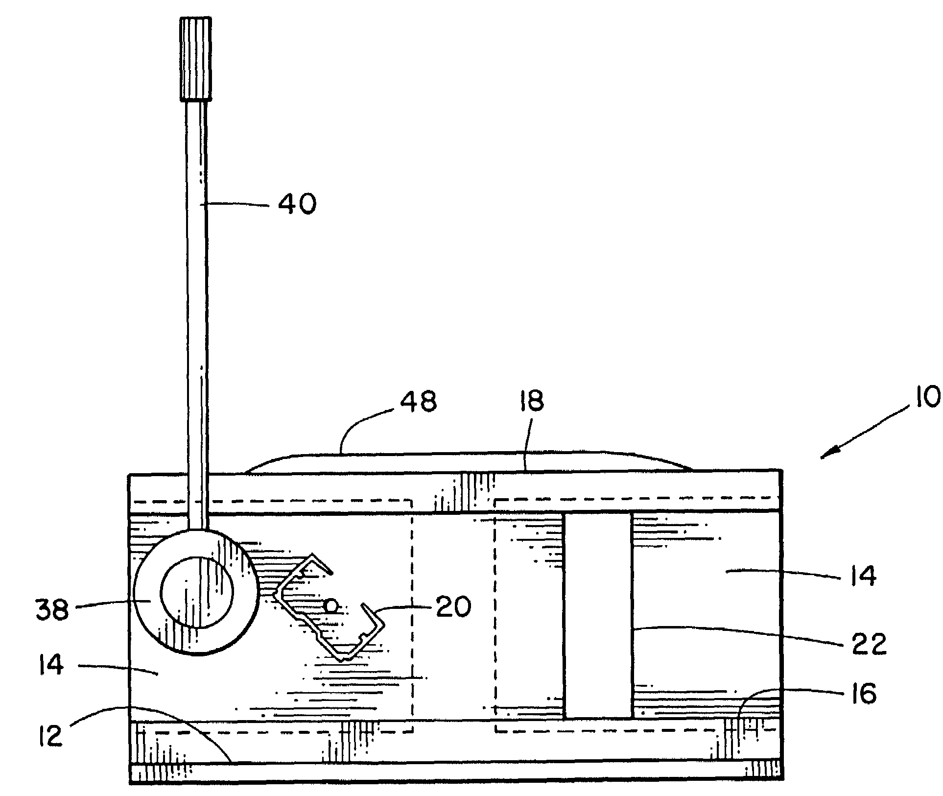
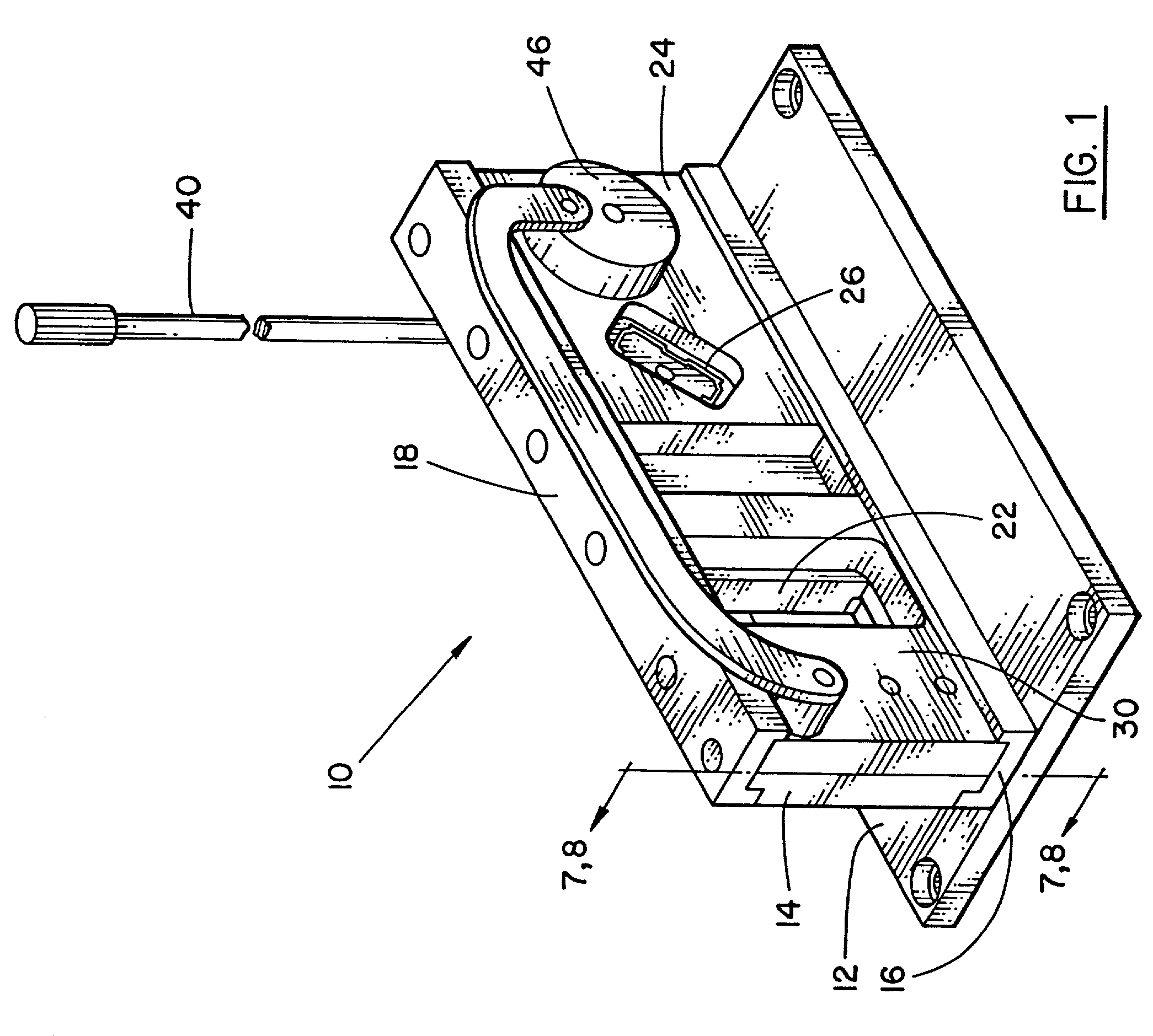
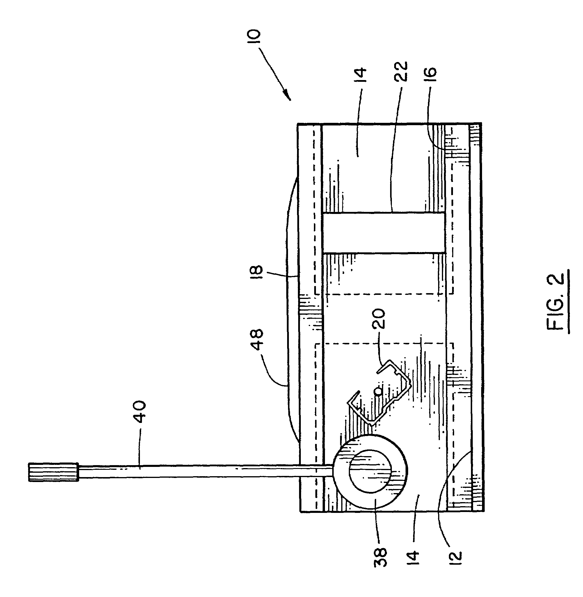
[0038]Referring to FIG. 1, the present invention is illustrated as an embodiment of an in-line cut down apparatus for trimming vertical blinds, indicated generally as 10. The apparatus 10 has a base plate 12 and a fixed component holder plate 14. The component holder plate 14 is secured to a lower channel 16, which is mounted on plate 12, and an upper channel 18 that is secured to the top edge of plate 14.

[0039]The holder plate 14 is provided with a head rail holder opening 20, and a blind covering component holder opening 22, (in this case blind slats).

[0040]The head rail opening 20 will clearly have to necessarily conform to the shape of the head rail of the particular blind being cut down. However, since the apparatus will normally be provided to the retail outlet by the manufacturer of the blinds, this presents no problem.

[0041]In some cases, it is conceivable that interchangeable dies could be provided, but it is believed to be an unnecessary and expensive refinement.

[0042]A mo...


PUM

PropertyMeasurementUnit
widthsaaaaaaaaaa
widthaaaaaaaaaa
heightaaaaaaaaaa

Abstract

A vertical blind cut down apparatus has a head rail holding plate with a head rail opening for receiving the head rail. The vertical blind cut down apparatus also has a cutting die to receive the head rail. The cutting die is movable relative to the holding plate for cutting one end of the head rail. The vertical blind cut down apparatus further has a blind holder with a blind material opening. The blind holder receives the blind materials. A blind cutting device is movable relative to the blind holder and cuts the blind material extending through the blind holder. The vertical blind cut down apparatus also has a first movement transmission for moving the head rail cutting die and a second movement transmission for moving the blind cutting device whereby both the blind materials and the head rail are cut.

Description

[0001]This application is a Continuation-in-Part of application Ser. No. 09 / 340,574 Filed Jun. 28, 1999 now abandoned.BACKGROUND OF THE INVENTION[0002]1. Field of the Invention[0003]The invention relates to a machine for trimming the ends of components of vertical blinds having a horizontal head rail and vertical strips or louvers.[0004]2. Description of the Prior Art[0005]In the past various apparatus has been designed for cutting down widths of specific designs, usually horizontal Venetian blinds. However, in general terms, these machines have not been totally suitable for cutting down both horizontal and vertical blinds, especially those being made from a variety of different materials. In addition, they have been somewhat more complex and costly than is required. In vertical blinds, the trolleys and the blind slats may be drawn along the head rail to one side or other of the window opening, or in some cases to both sides, and may be rotated between open and closed position, by a...

Claims


Application Information

Patent Timeline
Patent Type & Authority Patents(United States)
IPC IPC(8): B26D1/00B26D5/08B23D23/00B26D1/09B26D3/16E06B9/266
CPCB23D23/00B26D1/09E06B9/266B26D3/167Y10T29/39Y10T83/42Y10T83/412Y10T83/8727Y10T83/8843Y10T83/8748Y10T83/9411Y10T83/75
Inventor MAROCCO, NORBERT
Owner SHADE O MATIC
Why Eureka
Try Eureka