Digital micro mirror device and single-panel color projector using it

a digital micro mirror and color projector technology, applied in the direction of projectors, instruments, television systems, etc., can solve the problems of high cost of light valves, complex optical systems, and devices (e.g., projectors) using three light valves

Inactive Publication Date: 2002-10-01
IBM CORP +1
View PDF9 Cites 48 Cited by
  • Summary
  • Abstract
  • Description
  • Claims
  • Application Information

AI Technical Summary

Problems solved by technology

However, the cost of light valves is high, and thus the cost of a device (e.g., the projector) using three light valves has been very high.
Further, the optical system is also complicated, and thus the device is oversized.
The liquid crystal panel, of a transparent or reflective type, used in a three-panel liquid crystal projector is not capable of a response speed high enough for use in the color sequential display method.
However, PWM has low intensity since 2 / 3 of white light from a light source is lost when using a color disk.
However, because of the necessity of separating the color bands, this method makes the width of the bands narrower and a time to illuminate the light valve with the color bands shorter.
Therefore, it is impossible to acquire sufficient grayscales using PWM.
In addition, a very complicated control of PWM is necessary since a passing speed of the color bands changes in a non-linear manner because rotation of the prism and the timing for switching colors of the color band is different for each pixel line.
However, this method causes a phenomenon in which the three light beams overlap adjacent areas, and a problem arises in that the overlap area does not display the desired color.
Further, if a black mask or the like is placed among the three areas in order to prevent overlapping, the three areas cannot be displayed continuously as one image.

Method used


Image

  • Digital micro mirror device and single-panel color projector using it
  • Digital micro mirror device and single-panel color projector using it
  • Digital micro mirror device and single-panel color projector using it

Examples


Embodiment Construction

Referring now to the drawings, and more particularly to FIGS. 1-5, a preferred embodiment of the present invention is described.

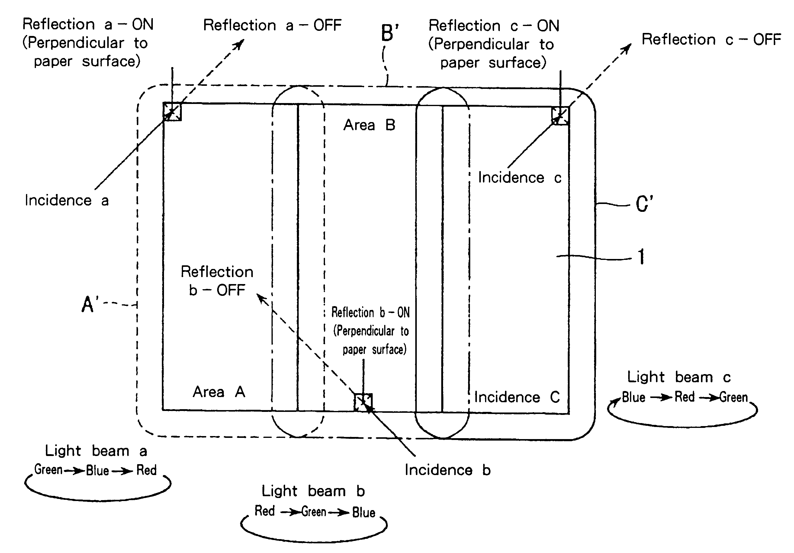
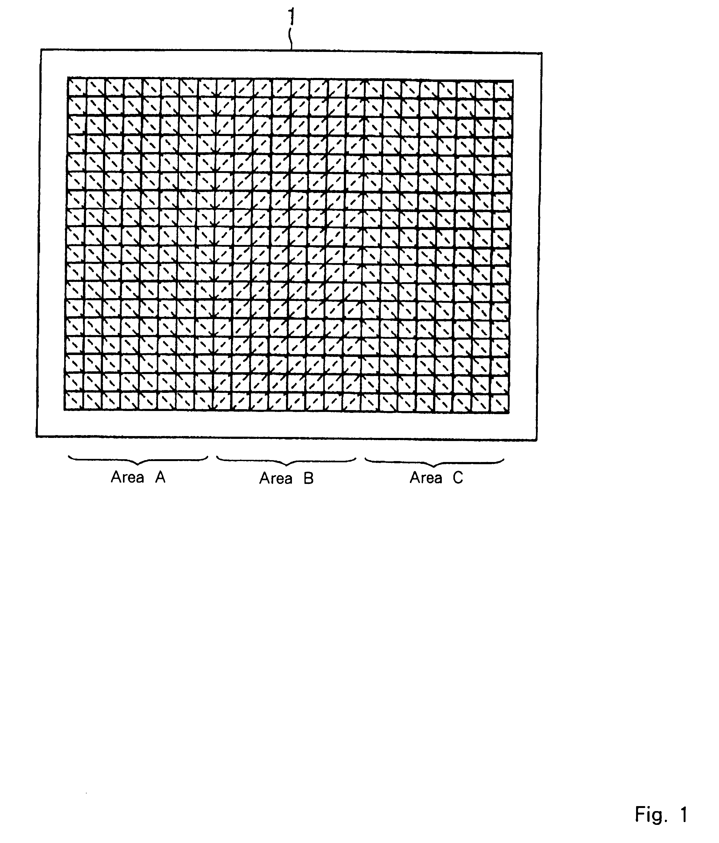
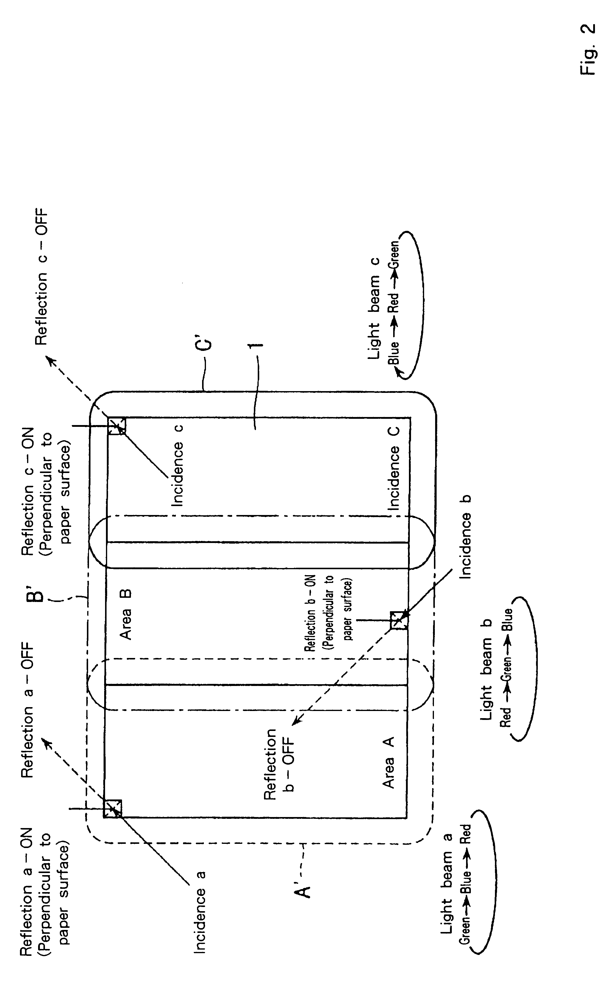
FIG. 1 illustrates a digital micro mirror device (DMD) 1 including a mirror portion divided into three areas (e.g., area A (left), area B (center) and area C (right)). The hinge rotating direction of the micro mirrors around a hinge in areas A and C is orthogonal to the rotation direction of the micro mirrors around a hinge in area B. For instance, if the hinged micro mirrors in areas A and C rotate around a diagonal line connecting upper left and lower right, the hinged micro mirrors in area B rotate around a diagonal line connecting lower left and upper right.

Each micro mirror part of the DMD 1 has a known configuration of a square mirror system placed on a static random access memory (SRAM). A hinge direction in a certain area can be changed merely by changing an electrode position of the SRAM, thereby to mount the mirror system rotated by 90 degrees fro...


PUM

PropertyMeasurementUnit
vertical angleaaaaaaaaaa
areaaaaaaaaaaa
colorsaaaaaaaaaa

Abstract

A digital micro mirror device (and a single-panel color projector using a digital micro mirror device) includes a reflection surface including an array of micro mirrors. The reflection surface is divided into two or more areas, and the axis direction about which a mirror of the array of micro mirrors rotates in one area is the same for all of the micro mirrors in the area. The single-panel color projector includes a white light source, a color separator for separating a white light from the white light source into two or more light beams, the digital micro mirror device reflecting the two or more light beams, an illumination light establishing unit for illuminating the two or more light beams from the color separator, and a projection unit for collecting and projecting light reflected from the digital micro mirror device.

Description

1. Field of the InventionThe present invention generally relates to a digital micro mirror device (DMD) and a single-panel color projector using the digital micro mirror device.2. Description of the Related ArtIn the field of color projectors, a projector that displays a brighter large-screen image is desirable. An example of such a projector is a conventional three-panel projector using three light valves including liquid crystal panels. This projector has been popular because it is easy to install, has good portability, and has high intensity. However, the cost of light valves is high, and thus the cost of a device (e.g., the projector) using three light valves has been very high. Further, the optical system is also complicated, and thus the device is oversized.Alternatively, in a color sequential display method, one light valve having a high response speed is used and light in the three primary colors is successively projected at high speed by a rotating color disk or the like. I...

Claims


Application Information

Patent Timeline
Patent Type & Authority Patents(United States)
IPC IPC(8): G02B26/08H04N9/31G02B27/18G03B21/00
CPCG02B26/0841H04N9/3114H04N9/3197
Inventor ISHIKAWA, YOSHIMOTOKANEKO, AKINORI
Owner IBM CORP
Why Eureka
Try Eureka