Thermal clip attachment apparatus for masonry anchors and methods thereof

a technology of wing nuts and clips, which is applied in the direction of walls, building components, building repairs, etc., can solve the problems of wing nuts being subjected to the elements, thread assemblies adding unnecessary costs to both the stud holder and the wing nut, and certain plastic materials being damaged

Active Publication Date: 2013-09-12
MECHANICAL PLASTICS CORP
View PDF19 Cites 51 Cited by
  • Summary
  • Abstract
  • Description
  • Claims
  • Application Information

AI Technical Summary

Benefits of technology

[0011]The thermal clip attachment can have many embodiments. One advantage of the merely exemplary emb

Problems solved by technology

One disadvantage of the current masonry anchor design is that the arrangement can cause abrasions if an installer's hand slips off of the drive mechanism and makes contact with the spinning wing nut attachment as the stud holder is driven into place.
These thread assemblies add unnecessary costs to both the stud holder and the wing nut.
Also, in some ins

Method used


Image

  • Thermal clip attachment apparatus for masonry anchors and methods thereof
  • Thermal clip attachment apparatus for masonry anchors and methods thereof
  • Thermal clip attachment apparatus for masonry anchors and methods thereof

Examples


Embodiment Construction

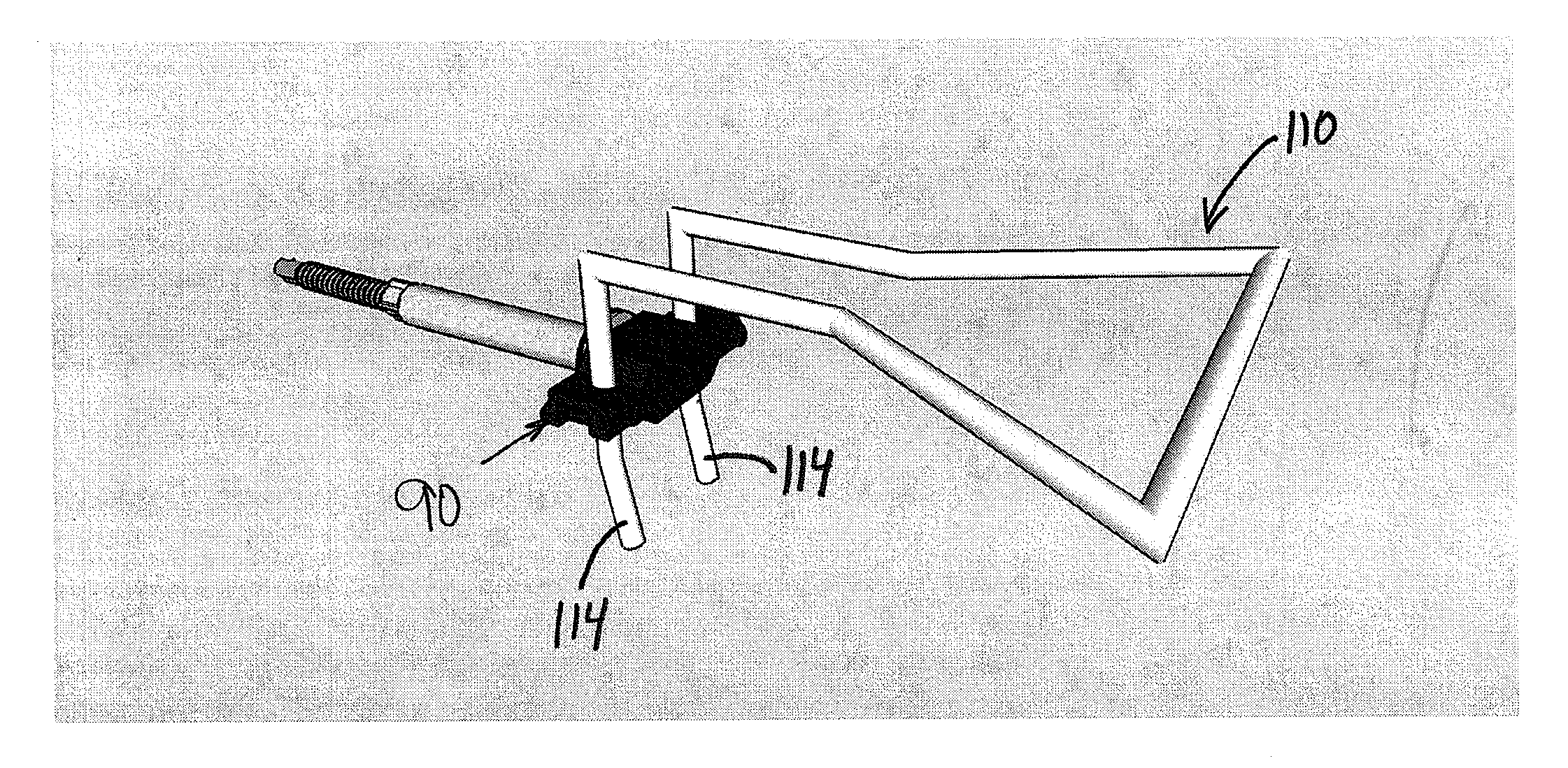
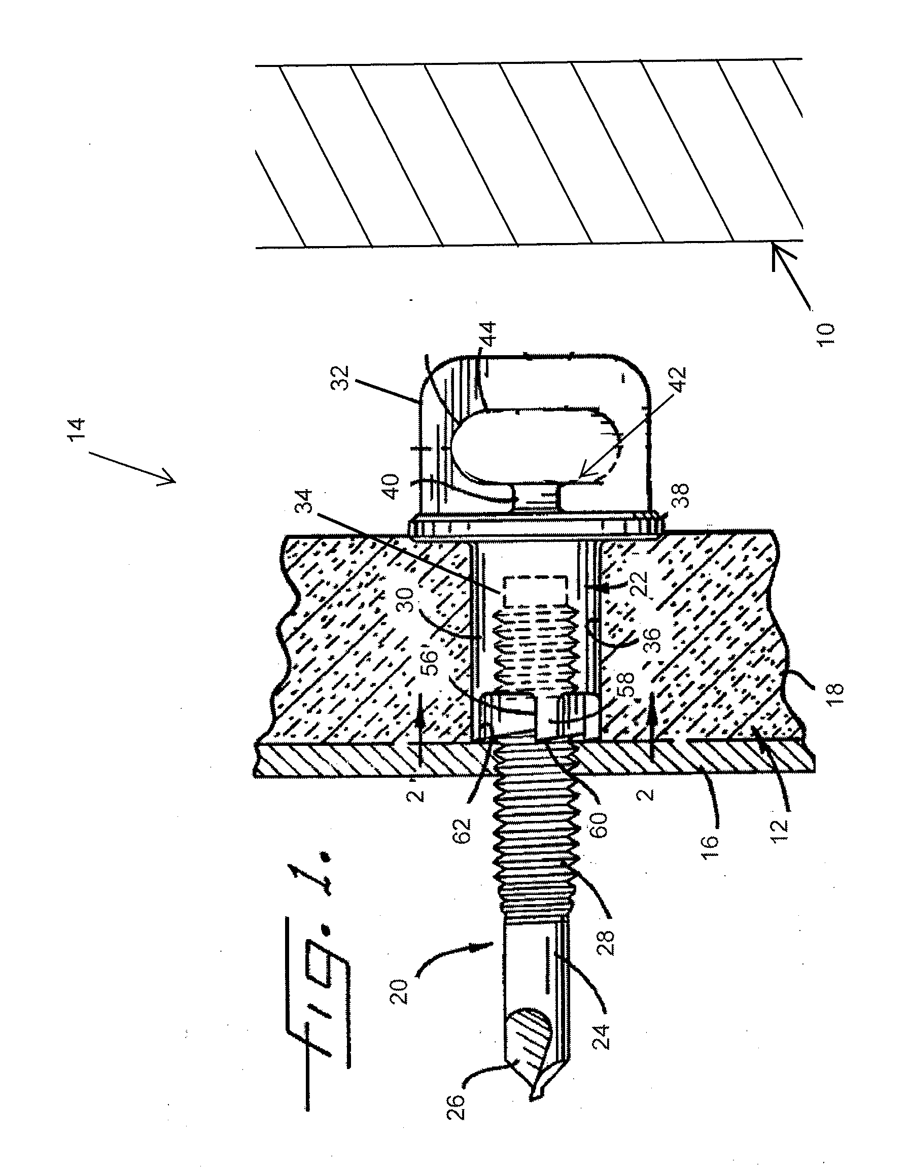
[0044]Before proceeding to a description of the thermal clip attachment apparatus and methods of using the same, it is helpful to discuss some of the other components used in a system for establishing a positive lateral load connection between an outer masonry veneer wall 10 and an inner structural supportive wall 12, such as the partial masonry anchoring system 14 shown in FIG. 1. Noticeably absent from FIG. 1 are a wire tie and the thermal clip attachment, which are described below with reference to FIGS. 9 through 19.

[0045]The outer masonry veneer wall 10 can be formed, for example, from bricks that are joined to one another by mortar or other cementitious material. In some embodiments, the inner structural supportive wall 12 may be formed by an inner sheet of thin steel 16 and by an outer layer 18 of hard, rigid, fire-resistant insulation, such as that sold by Weyerhaeuser under the trademark ULTRABOARD, for example.

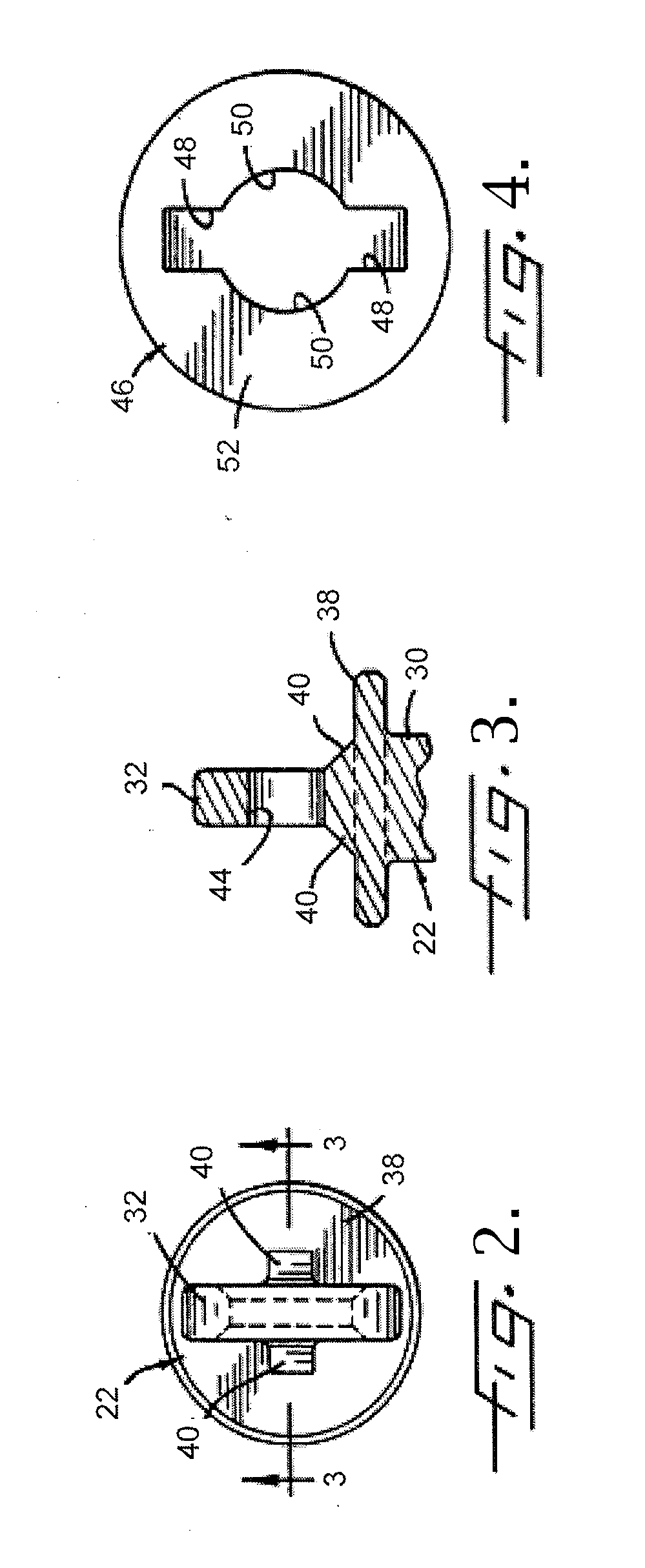
[0046]In general, the masonry anchoring system 14 may comprise ...


PUM


Abstract

A thermal clip attachment apparatus and methods for using the thermal clip attachment with a masonry veneer anchor system are disclosed. The thermal clip attachment may be a composite piece that attaches to the part of a stud that protrudes from an inner structural supportive wall after the stud is advanced into the wall. The thermal clip attachment serves as a thermal break between the stud and an outer masonry veneer wall. Further, the thermal clip attachment also serves as an attachment point for a wire tie, which allows a positive lateral load connection to be established between the outer masonry veneer wall and the inner structural supportive wall.

Description

PRIORITY STATEMENT[0001]This application claims the benefit of U.S. Provisional Application No. 61 / 602,178, filed Feb. 23, 2012.FIELD OF THE INVENTION[0002]The present invention relates generally to a masonry veneer anchor system and, more specifically, to a thermal clip attachment for a masonry veneer anchor system.BACKGROUND OF THE INVENTION[0003]Masonry veneer anchor systems are used to establish a positive lateral load connection between an outer masonry veneer wall and an inner structural supportive wall. Typically, one end portion of a self-drilling, self-tapping stud is screwed into a stud holder formed by a generally cylindrical barrel having an integral, tongue-like driving head on one end thereof. An eye for a wire tie is formed through the driving head while cutting elements are formed on the end of the barrel opposite the head.[0004]Oftentimes the stud is adapted to be driven by a power-rotated socket, which is sized and shaped to telescope into driving engagement with t...

Claims


Application Information

Patent Timeline
IPC IPC(8): E04B1/41E04B2/30
CPCE04B2/30E04B1/4178E04B1/388E04F21/1844
Inventor CURTIS, PAULSANCHEZ, DAVID
Owner MECHANICAL PLASTICS CORP
Why Eureka
Try Eureka