
CPU heat dissipating unit

a heat dissipating unit and cpu technology, applied in the direction of instruments, electrical apparatus casings/cabinets/drawers, semiconductor/solid-state device details, etc., can solve problems such as affecting the whole performance of the computer

Inactive Publication Date: 2006-09-19
HUNG KUO CHUAN
View PDF3 Cites 20 Cited by
  • Summary
  • Abstract
  • Description
  • Claims
  • Application Information

AI Technical Summary

Benefits of technology

[0005]A primary objective of the present invention is to provide a heat dissipating unit that can quickly dissipate a large quantity of heat energy away from the computer.
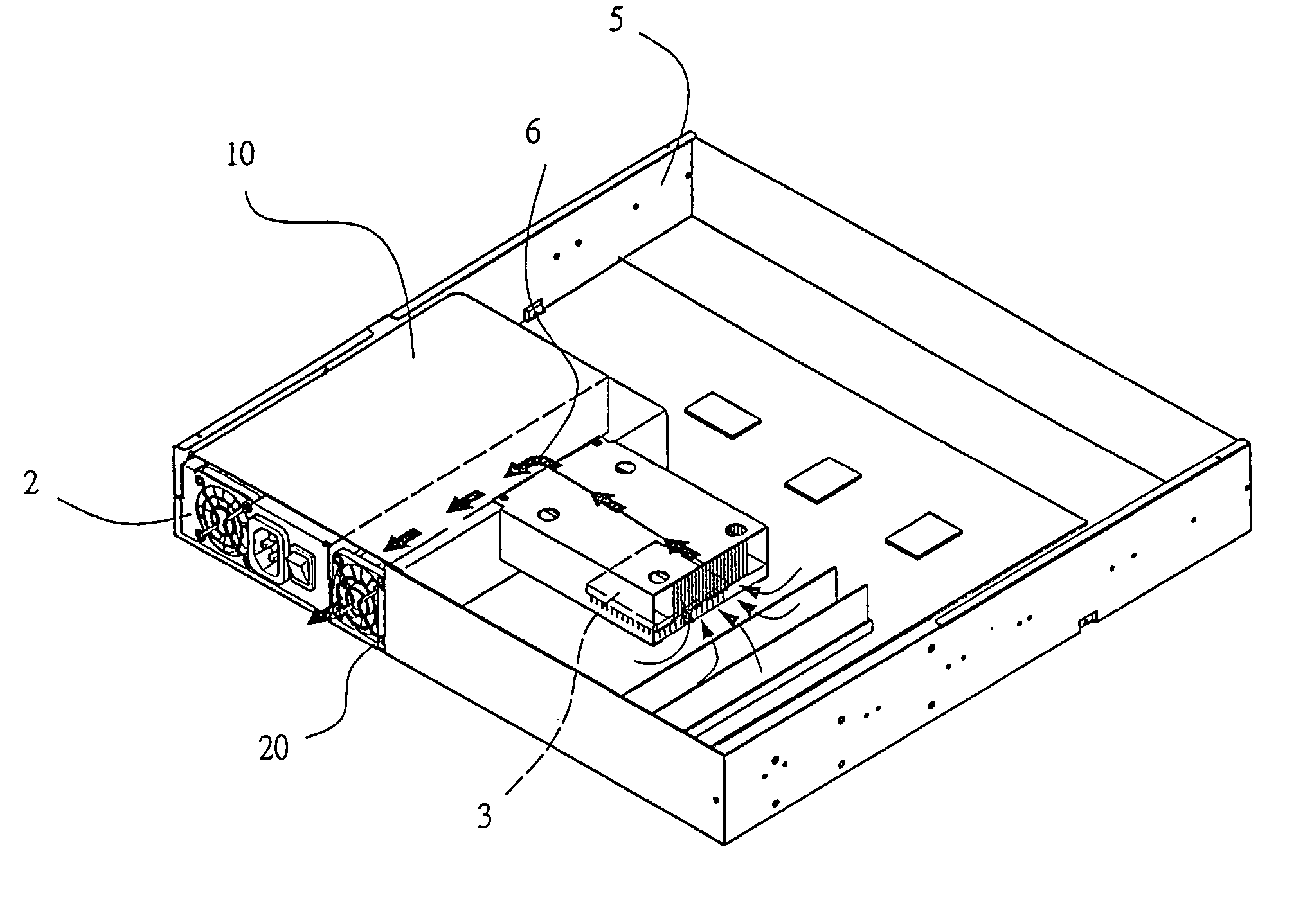
[0008]In the aforesaid structure, the cover unit is secured to the upper side of the power supply unit. Due to the outer casing of the power supply unit becoming an obstruction when inside the cover unit, the ventilation channel connects with the central processing unit. The central processing unit is situated at one end, while a cooling fan is assembled at the other end, allowing heat produced by the central processing unit to be directed out of the casing unit. This prevents the heat from returning to the casing unit and blocked by the other computer components forming concentrated heating points, influencing the whole performance of the computer.

Problems solved by technology

Due to the outer casing of the power supply unit becoming an obstruction when inside the cover unit, the ventilation channel connects with the central processing unit.
This prevents the heat from returning to the casing unit and blocked by the other computer components forming concentrated heating points, influencing the whole performance of the computer.

Method used


Image

  • CPU heat dissipating unit
  • CPU heat dissipating unit
  • CPU heat dissipating unit

Examples


Embodiment Construction

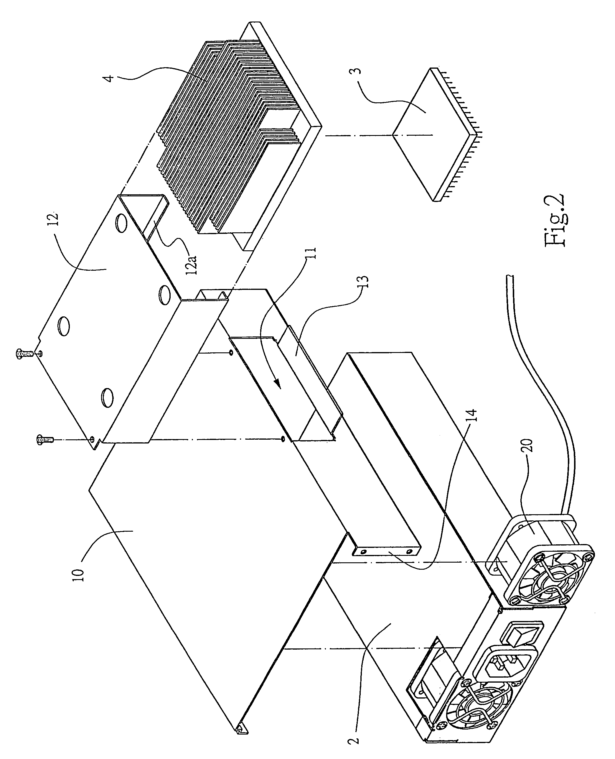
[0018]As shown in FIGS. 2, 3 and 4, a CPU (central processing unit) heat dissipating unit in a industrial computer includes a cover unit 10 and a cooling fan 20, wherein, the cover unit 10 is assembled on a upper side a power supply unit 2, permitting a ventilation channel 6 to form between the cover unit 10 and the power supply unit 2, in addition, an opening 11 is formed on a side of the cover unit 10, corresponding to the size for an opening of a tunnel unit 12. The tunnel unit 12 is assembled onto the opening 11, enabling connection with the central processing unit 3; in addition, a separating plate 13 is formed at a lower end of the open 11 to prevent the heat from a heat dissipating fin 4 to bypass there through. A securing plate 14 that attach to a casing unit 5 is assembled to a rear side of the cover unit 10 and to a side of the opening 11 respectively. The tunnel unit 12 is n-shaped, corresponding in size to the heat dissipating fin 4, moreover, a bending plate 12a bent in...


PUM


Abstract

A CPU heat dissipating unit for assembly into a 1U industrial computer, wherein, used to improve the effect of dissipating heat, mainly consisting of a cover unit, a tunnel unit and a heat dissipating fin. The cover unit is assembled to an upper side of a power supply unit, forming a ventilation channel between them. A heat dissipating unit is assembled on an upper side of the CPU and stored suitably into one side of the tunnel unit, while a cooling fan is assembled on the other side, thus providing quick dissipation of heat produced by the CPU.

Description

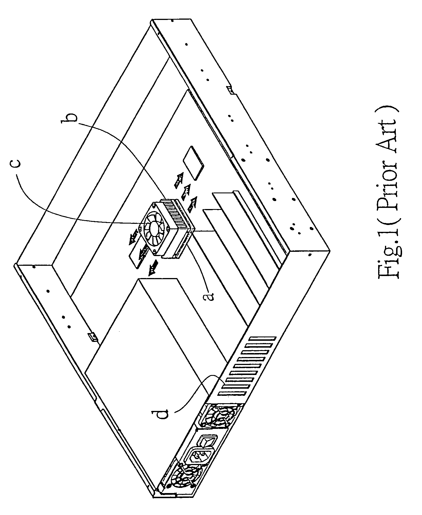
BACKGROUND OF THE INVENTION[0001](a) Field of Invention[0002]The present invention relates a CPU heat dissipating unit in a casing of 1U (1.75.inches.times.1) thin industrial computer, assembled to upgrade the heat dissipating process of a CPU, consisting of a covering unit, a tunnel unit and a cooling fan.[0003](b) Description of the Prior Art[0004]The body of an industrial computer is considerably smaller. Due to a CPU consistently processing, it not only consumes a large quantity of electricity, but also produces a large amounts of heat. Since the room in a casing to store heat is restricted, therefore the methods for dissipating heat are alike, refer to FIG. 1. A heat dissipating fin B is assembled above the CPU to direct the heat produced therein, then by assembling a cooling fan in the casing unit or on the heat dissipating fin thereafter, the heat is directed out of the casing unit. The heat dissipating fin B concentrates a large amount of heat in a short period of time, and ...

Claims


Application Information

Patent Timeline
Patent Type & Authority Patents(United States)
IPC IPC(8): H05K7/20F28F7/00G06F1/20H01L23/467
CPCG06F1/20H01L23/467H01L2924/0002H01L2924/00
Inventor HUNG, KUO-CHUAN
Owner HUNG KUO CHUAN
Learn More