
Method and apparatus for reducing trailing vortices in the wake of an aircraft

a technology of trailing vortices and wakes, which is applied in the direction of drag reduction, influencers by generating vortices, airflow influencers, etc., can solve the problems of generating harmful vortices in the wake of wings, and limiting the capacity of landing strips, so as to achieve rapid and effective dissipation of trailing vortex

Inactive Publication Date: 2003-02-04
AIRBUS OPERATIONS GMBH
View PDF26 Cites 47 Cited by
  • Summary
  • Abstract
  • Description
  • Claims
  • Application Information

AI Technical Summary

Benefits of technology

to provide a method and apparatus which assures a rapid dissipation of trailing vortices so that the formation of large scale vortices downstream of the aircraft is also reduced or even avoided;
to provide aircraft features that permit reducing the safety spacings between two aircraft in a landing approach while maintaining the required safety; and
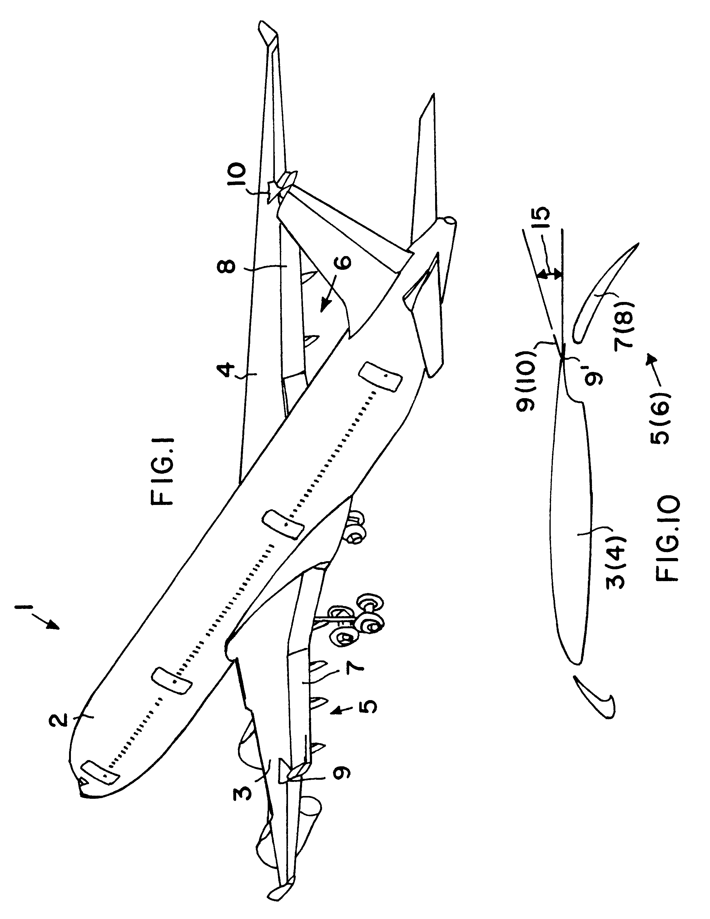
to reduce the trailing vortices by generating counteracting or interfering vortices in the critical locations where the trailing vortices are unavoidably generated at the wing especially by the landing flaps.
By rapidly dissipating the trailing vortices, the invention reduces or even avoids the formation of dangerous vortices downstream of the aircraft during slow flight especially during landing approach flight, whereby air traffic safety is generally increased. A further advantage of the invention is seen in that the regulation safety spacings between two landing aircraft can be reduced, whereby the capacity of a landing strip is increased, thereby accommodating the growing requirements of modern air traffic. The teachings of the invention are particularly suitable for use in large aircraft in which conventionally the formation of trailing vortices has posed a serious problem for air traffic. Moreover the present teachings provide a simple yet very efficient solution of the stated problems.
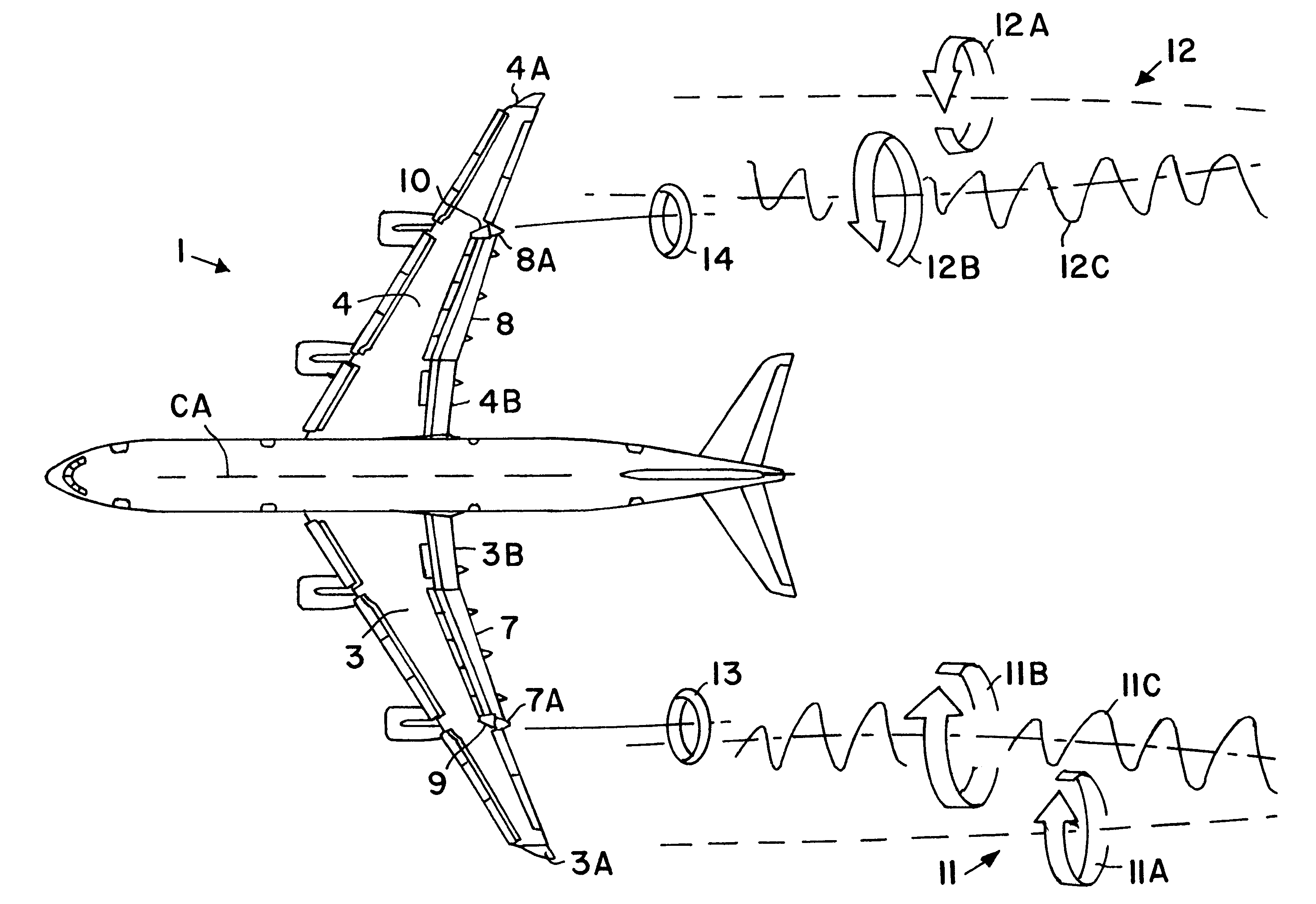
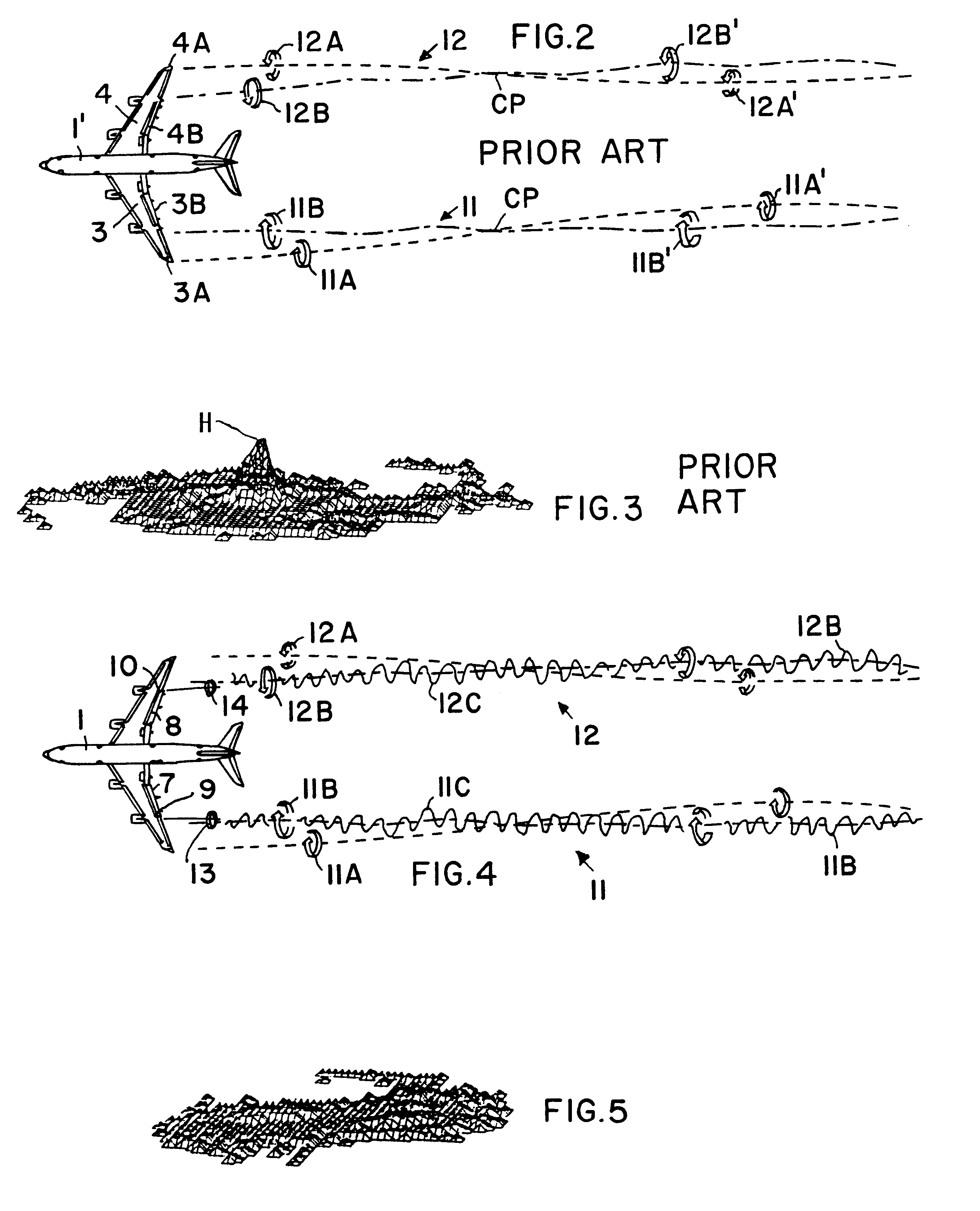
The method according to the invention is characterized in that a counter vortex is generated in said mounting area and this counter or control vortex is injected into the trailing vortex preferably at the outer end of the respective landing flaps, whereby the injection of the counter vortex causes the trailing vortex to vibrate relative to its propagation direction to thereby rapidly and effectively dissipate the trailing vortex.

Problems solved by technology

When a wing produces lift, harmful vortices are generated in the wake of the wings, particularly downstream of the landing flaps.
The trailing vortices produced in the wake of large aircraft pose a danger for any following aircraft, particularly in the dense flight patterns prevailing in landing approach paths.
Regulation safety spacings between two consecutive aircraft preparing for landing reduce the danger, but have the drawback of limiting the capacity of a landing strip.
However, the just described conventional features do not avoid the formation of large scale vortices downstream of the aircraft, yet do require an involved computer control program and system.
However, this conventional device due to its position and shape is not capable of producing a controlled interference or counter vortex for dissipating a respective trailing vortex.

Method used


Image

  • Method and apparatus for reducing trailing vortices in the wake of an aircraft
  • Method and apparatus for reducing trailing vortices in the wake of an aircraft
  • Method and apparatus for reducing trailing vortices in the wake of an aircraft

Examples


Embodiment Construction

FIG. 1 shows a perspective view of an aircraft 1 of a large scale, subsonic type having a body 2 constructed for transporting passengers. A left wing 3 and a right wing 4 are conventionally secured to the aircraft body 2. According to the invention the wing 3 is equipped with a controllable vortex generator 9 for producing a counter vortex for reducing a trailing vortex generated by a landing flap 7. A further controllable vortex generator 10 for producing a counter vortex is provided on the wing 4 at the outer end of a landing flap 8. The landing flap 7 with its accessories, not shown in detail, forms a high performance lift generating system 5. The landing flap 8 with its accessories not shown in detail forms a high performance lift producing system 6. The controllable vortex generators 9 and 10 are so positioned and constructed according to the invention that trailing vortices generated for example by the high performance landing flaps 7 and 8 will be at least reduced or rapidly ...


PUM


Abstract

Harmful trailing vortices downstream of an aircraft wing are at least partly dissipated by a respective counteracting vortex for each trailing vortex at each wing. An auxiliary counteracting vortex generating flap, preferably in the form of at least part of a delta wing, is journaled to the respective wing in the area of the outer end of a landing flap. The counteracting vortex is imposed on the respective trailing vortex, whereby the trailing vortex is caused to vibrate. The vibration dissipates the trailing vortex at least partially.

Description

PRIORITY CLAIMThis application is based on and claims the priority under 35 U.S.C. .sctn.119 of German Patent Application 100 18 389.1, filed on Apr. 13, 2000, the entire disclosure of which is incorporated herein by reference.The invention relates to an apparatus and to a method for reducing so-called trailing vortices that are generated by the high performance lift producing systems of the aircraft wings particularly the landing flaps.BACKGROUND INFORMATIONConventionally, the wings of aircraft, particular large subsonic transport aircraft are equipped with high performance lift producing systems such as landing flaps and their drives for generating the required lift, particularly during slow speed flight, for example during landing. Speeds above ground of about 200 miles per hour or less are referred to as slow speeds, that may vary depending on the type of aircraft. As a rule, such high performance lift producing systems comprise slats, landing flaps and their drives. When a wing...

Claims


Application Information

Patent Timeline
Patent Type & Authority Patents(United States)
IPC IPC(8): B64C23/00B64C23/06
CPCB64C23/06Y02T50/162Y02T50/10
Inventor HUENECKE, KLAUS
Owner AIRBUS OPERATIONS GMBH
Learn More