Server and cooler moduel arrangement

a server and cooler technology, applied in the field of server cooling technology, can solve the problems of reducing system stability and reliability, consuming a lot of electric energy of high-speed electronic devices, and releasing a lot of heat energy during operation, so as to achieve the effect of dispersing waste heat, quickly transporting waste heat away from the server, and reducing the amount of heat released

Active Publication Date: 2011-11-10
CHENBRO MICOM
View PDF0 Cites 51 Cited by
  • Summary
  • Abstract
  • Description
  • Claims
  • Application Information

AI Technical Summary

Benefits of technology

[0011]The present invention has been accomplished under the circumstances in view. It is one object of the present invention to provide a server and cooler module arrangement, which allows adjustment of the positions of cooling fans subject to the locations of the heat sources so that waste heat can be quickly carried away from the server during operation of the server.
[0012]To achieve this and other objects of the present invention, a server and cooler module arrangement comprises a server, and a cooler module mounted in the server for carrying waste heat out of the server efficiently. The server comprises an accommodation chamber, a partition way defined in the accommodation chamber, an operating system and an electronic device arranged in a stack in the accommodation chamber at one side relative to the partition way, an access device unit arranged in the accommodation chamber at an opposite side relative to the partition way, and a plurality of thermal zones located on an outer side of the operating system in communication with the space outside the server. The cooler module comprises a rack mounted in the partition way and having a plurality of open frames, and a plurality of fans respectively adjustably mounted in the open frames and respectively aimed at the operating system, the electronic device and the access device unit for drawing air or sending air toward the operating system, the electronic device and the access device unit to dissipate waste heat.
[0013]Further, the fans are adjustably mounted in the open frames of the rack at different elevations and respectively aimed at the operating system, the electronic device and the access device unit for drawing air or sending air toward different heat sources at the operating system, the electronic device and the access device unit for quick dissipation of waste heat.

Problems solved by technology

High-speed electronic devices consume much electric energy, and release much heat energy during operation.
If waste heat is not quickly carried away, the problems of electron ionization and thermal stress may occur, lowering system stability and reliability and shortening the lifespan of the electronic components.
Therefore, heat dissipation is an important issue to be settled.
The life cycle of computer becomes short to meet marketing requirement.
If waste heat from the CPU(s), IC chips, power supply device, CD-ROM and other electronic components of the operating system is not quickly dissipated, it will be accumulated in the computer, affecting normal functioning of the CPU(s), IC chips, power supply device, CD-ROM and electronic components of the operating system.
1. To fit different operation and control requirements, the server A may have new electronic parts and electronic devices A3 installed therein. When new electronic parts and electronic devices A3 are installed in the server A, the cooling fans B1 cannot be adjusted to send cooling air toward the new heat sources, causing accumulation of waste heat in the server A.
2. The circuit board A1 and the power supply device A2 may be respectively equipped with a respective mini fan for cooling. The working directions of the cooling fans B1 may be unable to effectively carry exhaust air of the mini fans of the circuit board A1 and the power supply device A2 away from the internal space of the server A, causing accumulation of waste heat in the server A.

Method used


Image

  • Server and cooler moduel arrangement
  • Server and cooler moduel arrangement
  • Server and cooler moduel arrangement

Examples


Embodiment Construction

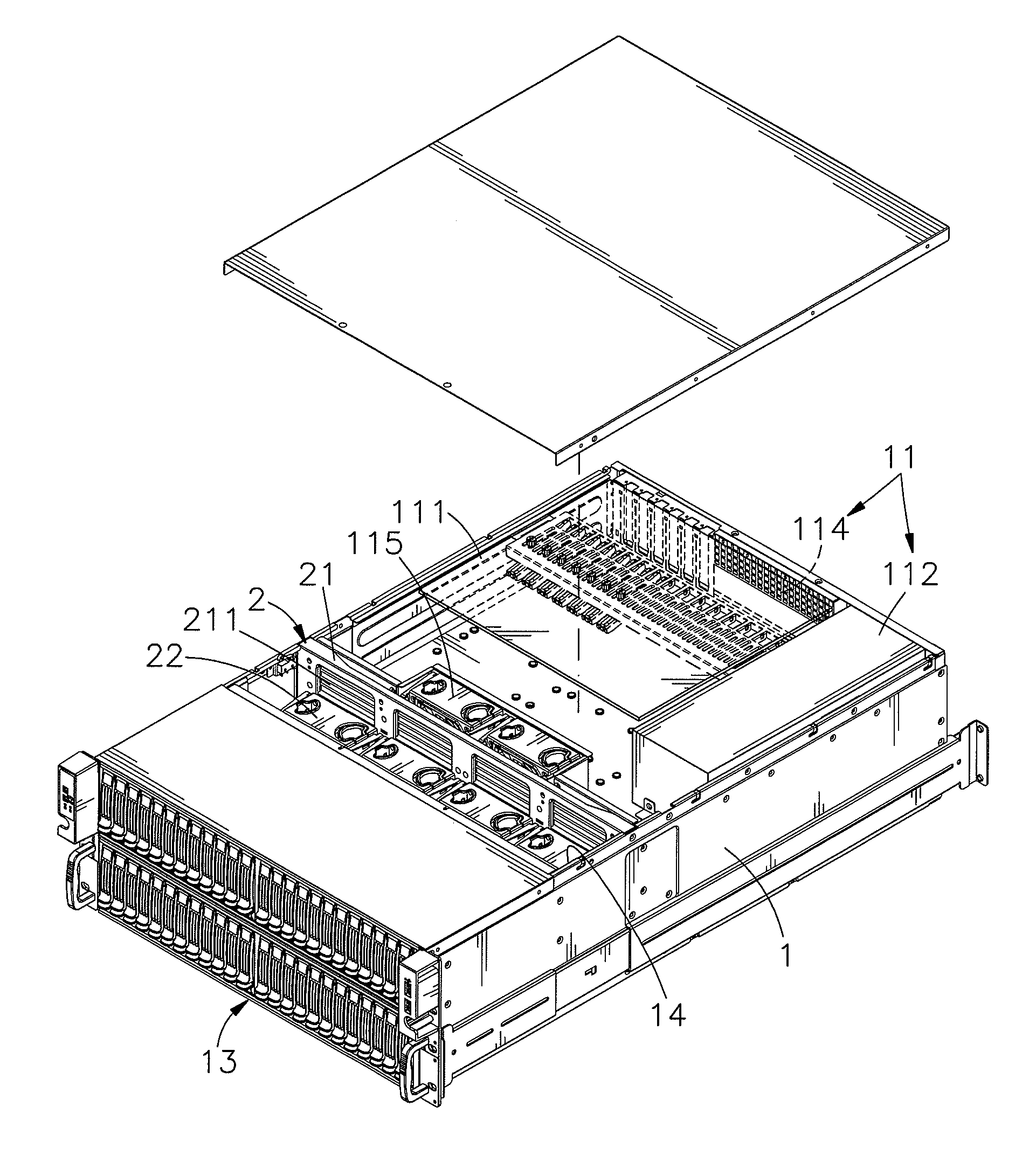
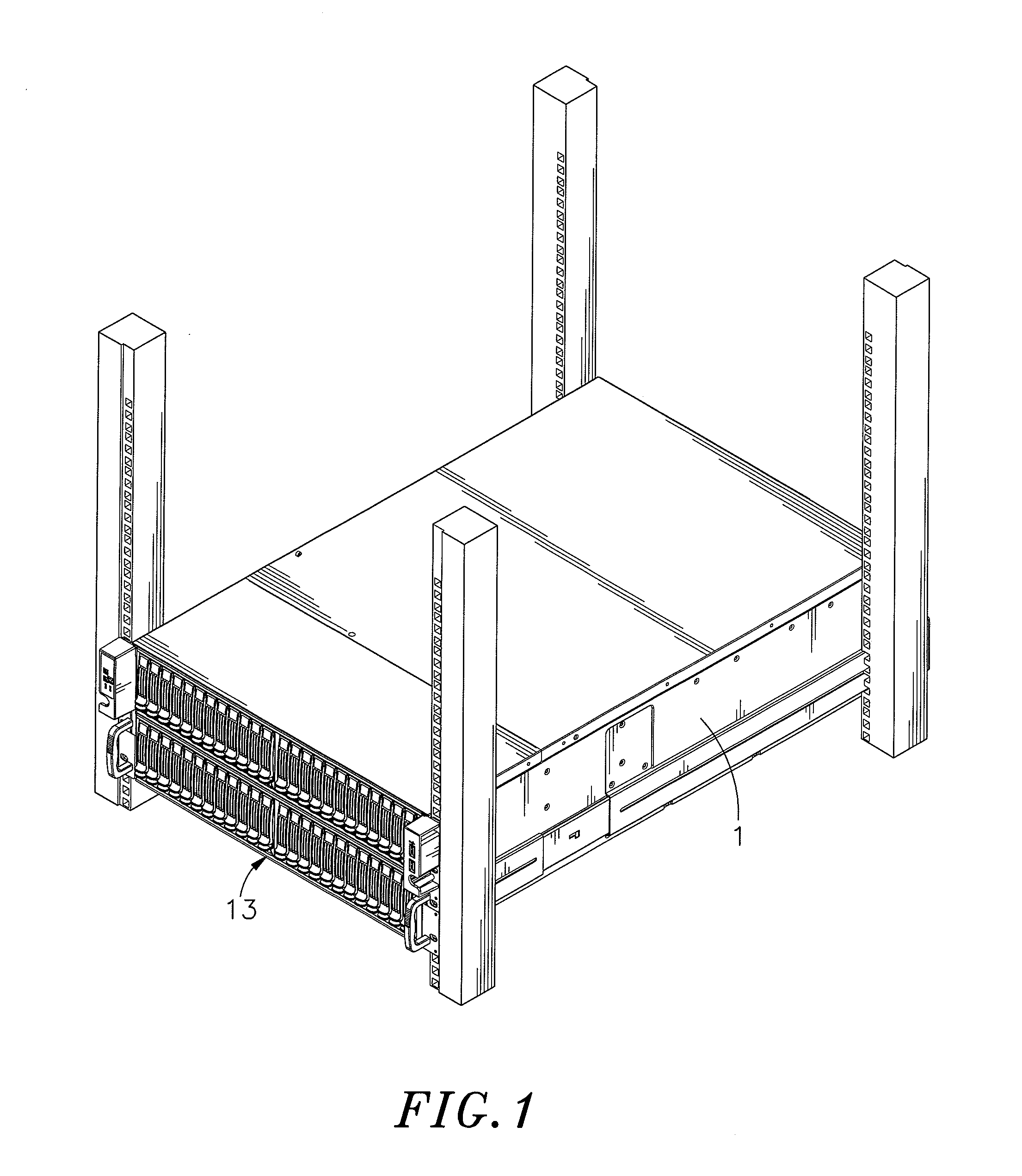
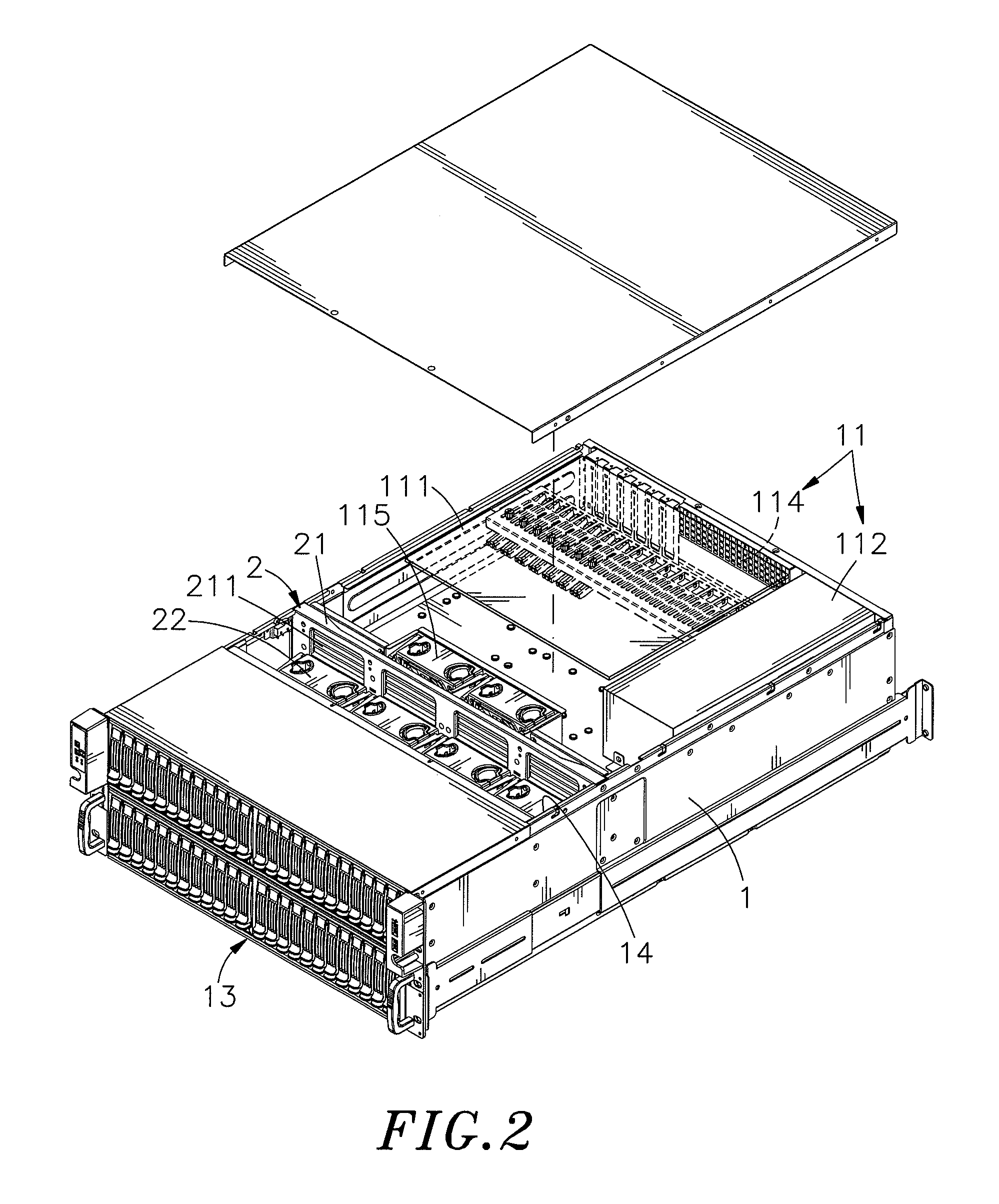
[0021]Referring to FIGS. 1˜5, a server and cooler module arrangement in accordance with the present invention is shown comprising a server 1 and a cooler module 2.

[0022]The server 1 comprises an accommodation chamber 10, an operating system 11 and an electronic device 12 arranged in a stack in the accommodation chamber 10 at one side, an access device unit 13 arranged in the accommodation chamber 10 at an opposite side, and a partition way 14 defined between the stack of the operating system 11 and electronic device 12 and the access device unit 13. The operating system 11 comprises a circuit board 111 carrying a circuit layout, a power supply device 112 and other requisite electronic components, an isolation frame 113 covering the circuit board 111 and the power supply device 112 and a plurality of thermal zones 114 located on the isolation frame 113 adjacent to the circuit board 111 in communication between the space inside the operating system 11 and the space outside the server ...


PUM


Abstract

A server and cooler module arrangement includes a server accommodating a stack of an operating system and an electronic device in an accommodation chamber therein at one side and an access device unit in the accommodation chamber at an opposite side, and a cooler module, which comprises a rack mounted in a partition way in the accommodation chamber between the stack of operating system and electronic device and the access device unit and a plurality of fans respectively adjustably mounted in respective open frames at different elevations and adapted for drawing air or sending air toward different heat sources in the operating system, the electronic device and the access device unit for quick dissipation of waste heat.

Description

BACKGROUND OF THE INVENTION[0001]1. Field of the Invention[0002]The present invention relates to server cooling technology and more particularly, to a server and cooler module arrangement, which has fans arranged at different elevations to aim at different heat sources for quick dissipation of waste heat during operation of the server.[0003]2. Description of the Related Art[0004]Following fast development of semiconductor technology, the packaging density of electronic devices is comparatively higher, and the size of electronic devices is comparatively smaller. High-speed electronic devices consume much electric energy, and release much heat energy during operation. If waste heat is not quickly carried away, the problems of electron ionization and thermal stress may occur, lowering system stability and reliability and shortening the lifespan of the electronic components. Therefore, heat dissipation is an important issue to be settled.[0005]Nowadays, computer has been intensively use...

Claims


Application Information

Patent Timeline
Patent Type & Authority Applications(United States)
IPC IPC(8): G06F1/20
CPCH05K7/20727
Inventor CHEN, PO-CHING
Owner CHENBRO MICOM
Why Eureka
Try Eureka