Lubricant applicator

a technology of lubricant applicators and grease, applied in the direction of rail wetting/lubrication, rail lubrication, locomotives, etc., can solve the problems of unsatisfactory use of grease or oil applied directly to the flange of the wheel, unsatisfactory load stress and wheel flange wear, and require a lot of maintenance, so as to achieve the effect of quick and convenient chang

Inactive Publication Date: 2006-09-19
MITROVICH MICHAEL J +1
View PDF6 Cites 7 Cited by
  • Summary
  • Abstract
  • Description
  • Claims
  • Application Information

AI Technical Summary

Benefits of technology

[0003]In order to overcome problems inherent in the prior art there has been devised by the present invention a lubricant applicator that can be used in numerous applications. Many of the applications described hereinafter will refer to locomotive applications, but the present invention is useful in any application where a solid lubricant can be applied, particularly to a metal surface. Several examples of this could be crane wheels and logging drag chains. The lubricant applicator of the present invention generally comprises a combination holder and dispenser for a lubricant, having a lubricant generally in the form of a stick, inserted inside the combination holder and dispenser, whereby lubricant is disposed from the same portion of the combination holder and dispenser as the lubricant stick was inserted, in the rear portion of the combination holder and dispenser. From the rear portion of the combination holder and dispenser the lubricant is disposed out of the front portion of the combination holder and dispenser and onto a position where it will be ultimately disposed. If that position is on a locomotive, the position may be on a wheel flange as will be described hereinafter, but the position could be other positions on a train. Another example of where the lubricant can be disposed is onto heavy drive chains. A variable attaching member attaches the combination holder and dispenser to a pre-existing or other mounting member in a position in proximity to the position to where it will be disposed. The variable attaching member of the present invention varies according to the application in which it is used. A dispensing system in the form of a constant force system is in contact with the combination holder and dispenser to apply constant force to the rear portion of the combination holder and dispenser so that the lubricant, generally in stick form, is dispensed at a constant rate from the rear portion and out of the front portion of the combination holder and dispenser. The constant force system is comprised of a positioning member in the form of a spring holder and slide mechanism that holds a constant force actuator in the form of a spring. A locking member in the form of a pin, holds the spring holder and slide mechanism and spring at a constant force against the lubricant within the combination holder and dispenser. In this way, the combination holder and dispenser applies a new lubricant from the rear portion of the combination holder and dispenser and out through the front portion of the combination holder and dispenser. Furthermore, a lubricant stick can be changed without removing the combination holder and dispenser from the variable attaching member. A lubricant stick can therefore be changed quickly and conveniently without the use of any tools. A lubricant stick is changed by removing the spring holder and slide mechanism, inserting a lubricant stick and then re-positioning the spring holder and slide mechanism in place to hold the spring in place. The combination holder and dispenser, therefore, never has to be moved or removed from its position.

Problems solved by technology

Heavier loads also add increased load stress and wheel flange wear.
In the prior art, the use of grease or oil applied directly to the flange of a wheel, often with a spray, has been unsatisfactory because of major maintenance problems and difficulty in controlling where the grease or oil is applied.
However, these still require much maintenance and their reliability in withstanding a harsh working environment has not been shown.
One of the problems of maintenance of these systems is that pre-existing mounting members are often attached to a locomotive car in proximity to a wheel flange.
This is very time consuming and requires the availability of specialized tools at the scene.

Method used


Image

  • Lubricant applicator
  • Lubricant applicator
  • Lubricant applicator

Examples


Embodiment Construction

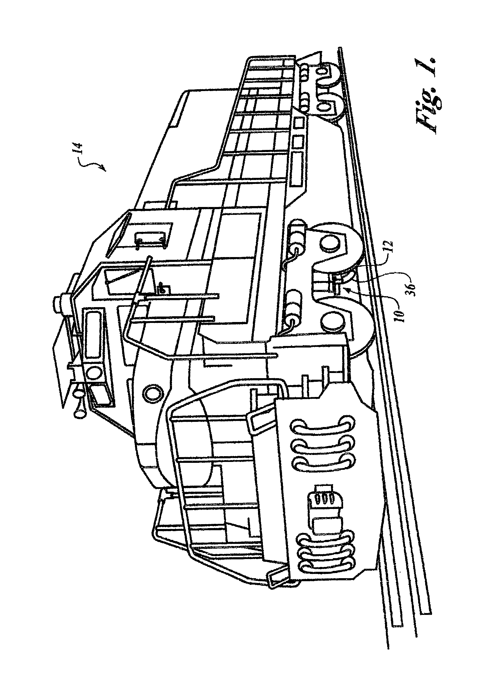
[0013]Referring now to the drawings in general and in particular to FIG. 1 of the drawings, there is shown an environmental perspective view of the lubricant applicator of the present invention showing how the device is positioned in proximity to the wheel flange of a locomotive. While FIG. 1 shows the example of the present wheel flange lubricant applicator being used on a locomotive, it is to be understood that this is only an example, and the applicator of the present invention can be used in any number of other applications where a stick lubricant can be used on a metal surface, such as crane wheels and logging drag chains. Also, while the lubricant applicator of the present invention is shown used on a locomotive, it is also within the spirit and scope of the invention that it be used on a rail car.

[0014]In FIG. 1 the lubricant applicator of the present invention is shown generally by the number 10. The applicator 10 is positioned in proximity to the wheel flange 12 of the loco...


PUM


Abstract

A lubricant applicator for disposing lubricant onto a metal surface. The lubricant applicator generally includes a combination holder and dispenser. Lubricant is disposed from the same portion of the combination holder and dispenser as the lubricant was inserted, in the rear portion of the combination holder and dispenser. A dispensing system applies constant force to the rear portion of the combination holder and dispenser so that lubricant is disposed from the rear portion and out of the front portion of the combination holder and dispenser. Lubricant, generally in the form of a stick, can therefore be easily replaced without removing the applicator from its location or without removing its mounting arrangement. Various applications and mounting arrangements for the lubricant applicator are disclosed, as is a method for providing a lubricant applicator.

Description

[0001]Applicant hereby claims priority of provisional patent application 60 / 335,766 filed on Dec. 5, 2001.BACKGROUND OF THE INVENTION[0002]For many years, there has been a desire for lubricant applicators in numerous applications, particularly involving heavy machinery or locomotives. In particular, for over fifty years railroads and transit systems have tried to reduce destructive wear to wheel flanges that occurs on various cars and parts of the system. Wear is caused when a wheel flange contacts the gauge face of the track when the car is passing through a curve and when the car moves sideways while in a straight or tangent track. Heavier loads also add increased load stress and wheel flange wear. In the prior art, the use of grease or oil applied directly to the flange of a wheel, often with a spray, has been unsatisfactory because of major maintenance problems and difficulty in controlling where the grease or oil is applied. To overcome these difficulties, solid stick lubricant...

Claims


Application Information

Patent Timeline
Patent Type & Authority Patents(United States)
IPC IPC(8): B61K3/00B61C17/08B61K3/02F01M9/12F16H57/05
CPCB61K3/02F16H57/05
Inventor MITROVICH, MICHAEL JBOYER, BERNARD L.
Owner MITROVICH MICHAEL J
Why Eureka
Try Eureka