Clamp with magnetic spindle positioner

a positioner and magnetic spindle technology, applied in the field of positioning devices, can solve problems such as the shifting of the spindle from the desired position, and achieve the effect of substantially reducing the chance of spindle shifting or slippage during arm movemen

Active Publication Date: 2006-09-19
THE BOEING CO
View PDF11 Cites 19 Cited by
  • Summary
  • Abstract
  • Description
  • Claims
  • Application Information

AI Technical Summary

Benefits of technology

[0008]The block is installed in the arm channel through the open arm end, and then the spindle is threaded into the block through the slot in the top wall of the clamp arm. When the bottom end of the spindle emerges through the slot in the bottom wall of the arm, the clamp foot is threaded onto the spindle. The magnet in the block is situated so that its is closely proximate one of the side walls of the arm, whereby the magnetic field established between the magnet and the arm maintains the block (and thus the spindle threaded through it) in any

Problems solved by technology

Movement of the clamp arm between its raised and lowered positions while the nuts or fasteners are loose can result in the spindle shifting from

Method used


Image

  • Clamp with magnetic spindle positioner
  • Clamp with magnetic spindle positioner
  • Clamp with magnetic spindle positioner

Examples


Embodiment Construction

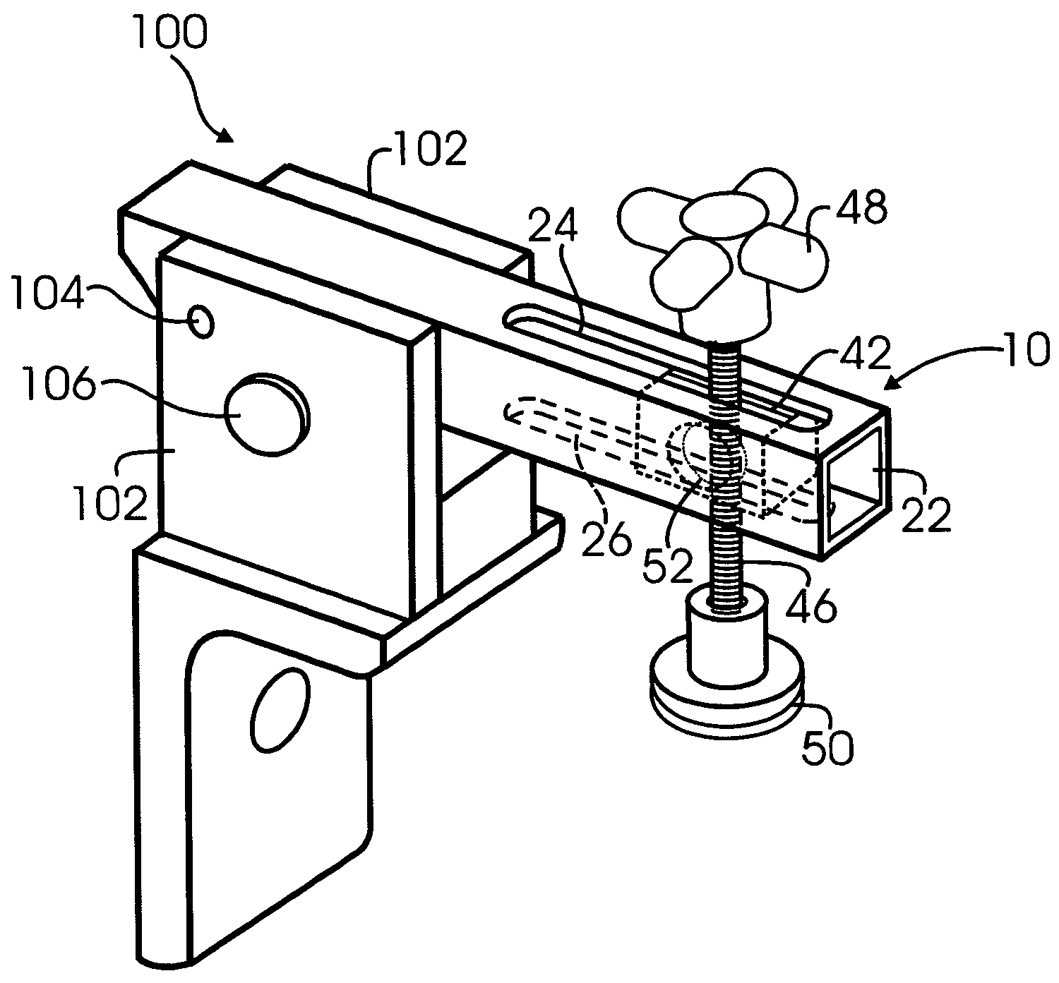
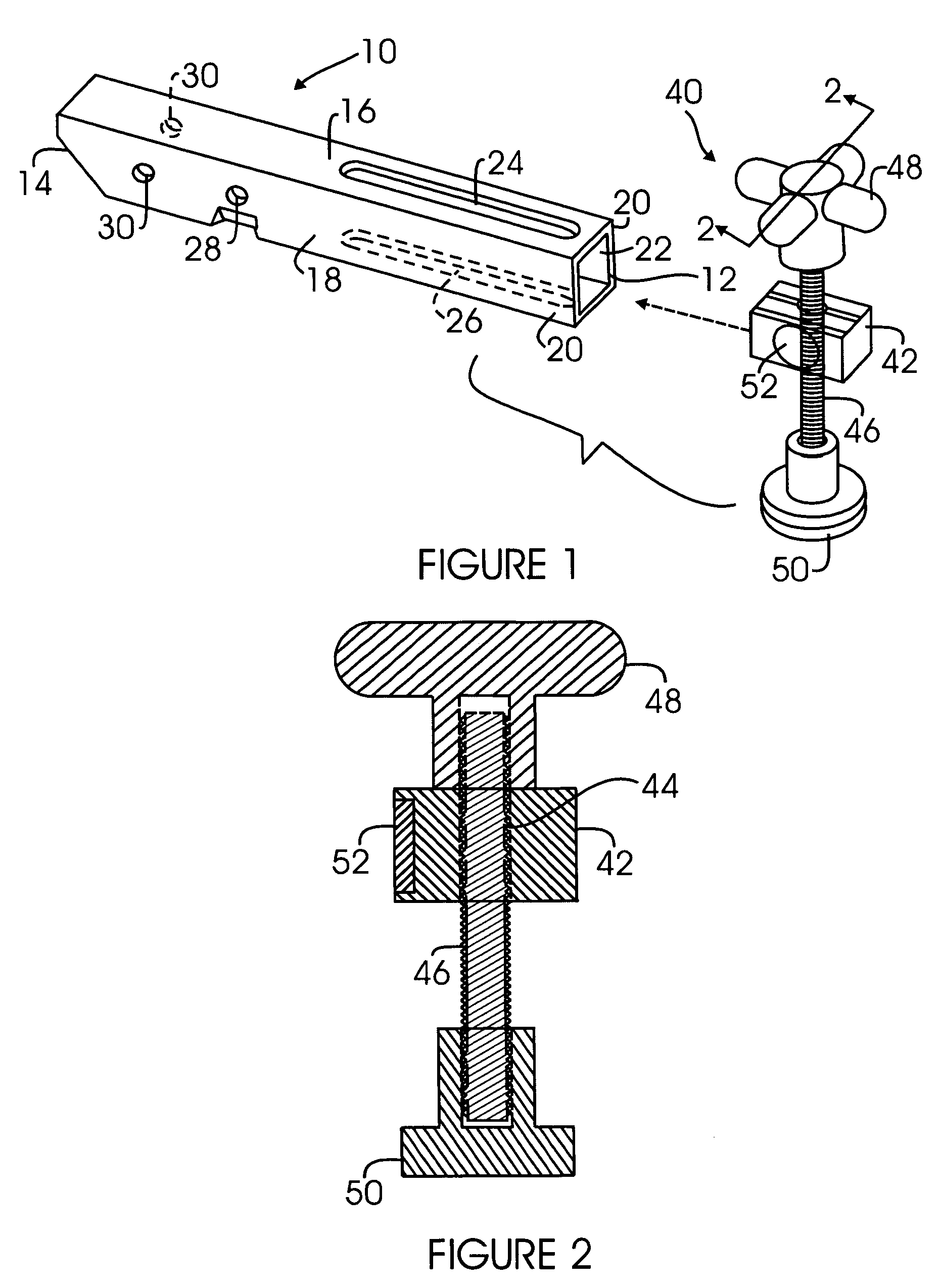
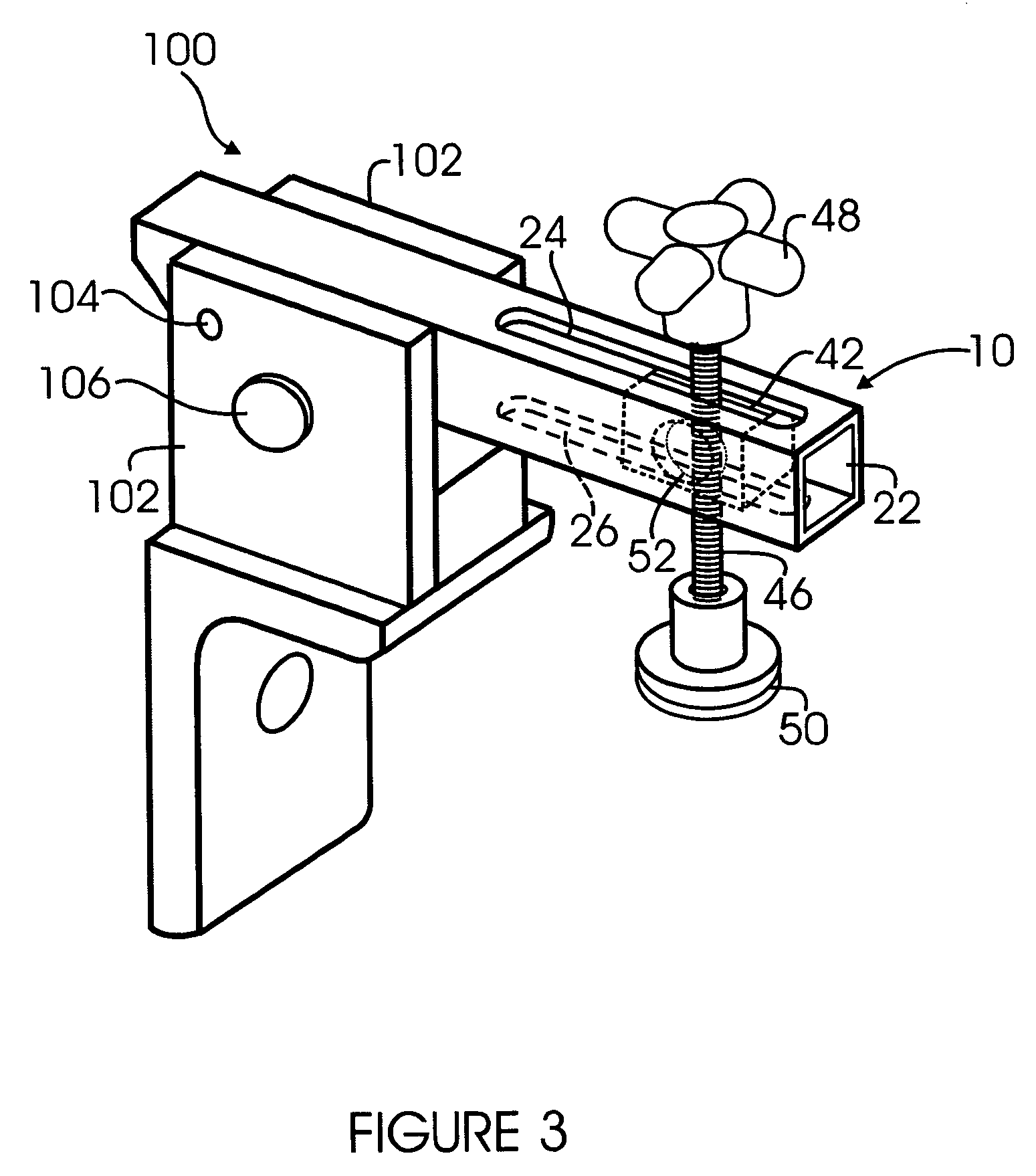
[0013]Referring now to the drawings, FIGS. 1 and 2 illustrate a clamp arm 10 and a clamp spindle assembly 40, of the type used in an improved clamping apparatus 100 (FIG. 3) in accordance with the present invention. The arm 10 comprises a hollow tube of a magnetizable (i.e., ferrous) metal (preferably a suitable structural steel) having an open first or clamping end 12 and second or pivoting end 14 that may be closed or open. The arm is preferably rectangular in cross-section, with a top wall 16, a bottom wall 18, and side walls 20 that define a rectangular interior channel 22. A first longitudinal slot 24 is formed in the top wall 16, and a second longitudinal slot 26, in registry with the first slot 24, is formed in the bottom wall 18. The arm 10 may also be provided with a locking pin aperture 28 in one of the side walls 20, and a registered pair of pivot pin apertures 30 in the side walls 20, near the second end 14 of the arm 10.

[0014]The clamp spindle assembly 40 is mounted for...


PUM

PropertyMeasurementUnit
Lengthaaaaaaaaaa
Magnetic forceaaaaaaaaaa

Abstract

A clamping apparatus includes a clamp arm that is pivotable between a raised position and a lowered position, and a clamp spindle assembly that is adjustably positionable along the length of the arm. A magnet in the clamp spindle assembly magnetically engages the clamp arm with sufficient magnetic force to maintain the spindle assembly in a selected position as the clamp arm is moved between its raised and lowered positions, while allowing the position of the clamp spindle assembly to be manually adjusted.

Description

CROSS-REFERENCE TO RELATED APPLICATION[0001]Not ApplicableFEDERALLY-SPONSORED RESEARCH OR DEVELOPMENT[0002]Not ApplicableBACKGROUND OF THE INVENTION[0003]This invention relates to clamping devices for holding a workpiece during assembly or manufacture. More specifically, it relates to an adjustable clamp having a locking clamp spindle that is adjustably positionable in a clamping arm, wherein the spindle can be maintained in a desired position in the arm by means of a permanent magnet fixed to the spindle.[0004]Clamps for holding workpieces typically include a clamping spindle that is installed in a pivotable clamp arm and that is adjustably positionable along the length of the clamp arm. The spindle is held in a desired position by means of spindle locking nuts or similar fasteners. To adjust the position of the spindle on the clamp arm, the nuts or fasteners are loosened, and the spindle is re-positioned. Movement of the clamp arm between its raised and lowered positions while the...

Claims


Application Information

Patent Timeline
IPC IPC(8): B23C9/00
CPCB25B5/10B25B5/163Y10T409/303752Y10T409/309016Y10T483/16
Inventor COLBURN, BILL D.ALLARD, ROBERT W.DIXON, ROBERT D.
Owner THE BOEING CO
Why Eureka
Try Eureka