Cleaning brush structure with replaceable brush hair plate

a brush and hair plate technology, applied in the field of cleaning brushes, can solve the problems of occupying too much storage space, wasting earth resources, and unable to remove, replace or clean the hair plate after a long time us

Inactive Publication Date: 2006-09-26
YU SHU FENG
View PDF6 Cites 10 Cited by
  • Summary
  • Abstract
  • Description
  • Claims
  • Application Information

AI Technical Summary

Benefits of technology

[0011]The primary objective of the present invention is to provide a structure for improving the prior-art design of integrally coupling the plate body and the brush hair plate that causes the brush hair plate unable to be replaced or cleaned and creates the problems of wasting resources and creating inconvenience and troubles to users. With the design of accommodating groove being tapered in width from its front end to its rear end on the plate body of the cleaning brush, the baseboard being tapered in width from its front end to its rear end, and the opening above the accommodating groove being slightly smaller than its bottom according to the present invention, the baseboard can have an advantage of being secured into the accommodating groove, and thus the baseboard will not fall off easily. In the meantime, the accommodating groove has an opening being disposed above the accommodating groove and slightly smaller than the bottom of the accommodating groove and its rear end is broader than its front end, such that when a user takes out the baseboard for replacement or cleaning, the baseboard will not come out uncontrollably due to the excessively applied force. In the meantime, the present invention concurrently has the economic effect and complies with the environmental protection requirements.

Problems solved by technology

In view of the description above, the design of integrally coupling the plate body of the cleaning brush with the brush hair plate causes the brush hair plate unable to be removed, replaced, or cleaned after a long-time use.
Since the brush hair plate cannot be replaced, therefore users have to buy a new set of cleaning brush, which not only wastes earth resources, but also has a drawback of occupying too much storage space.

Method used


Image

  • Cleaning brush structure with replaceable brush hair plate
  • Cleaning brush structure with replaceable brush hair plate
  • Cleaning brush structure with replaceable brush hair plate

Examples


Embodiment Construction

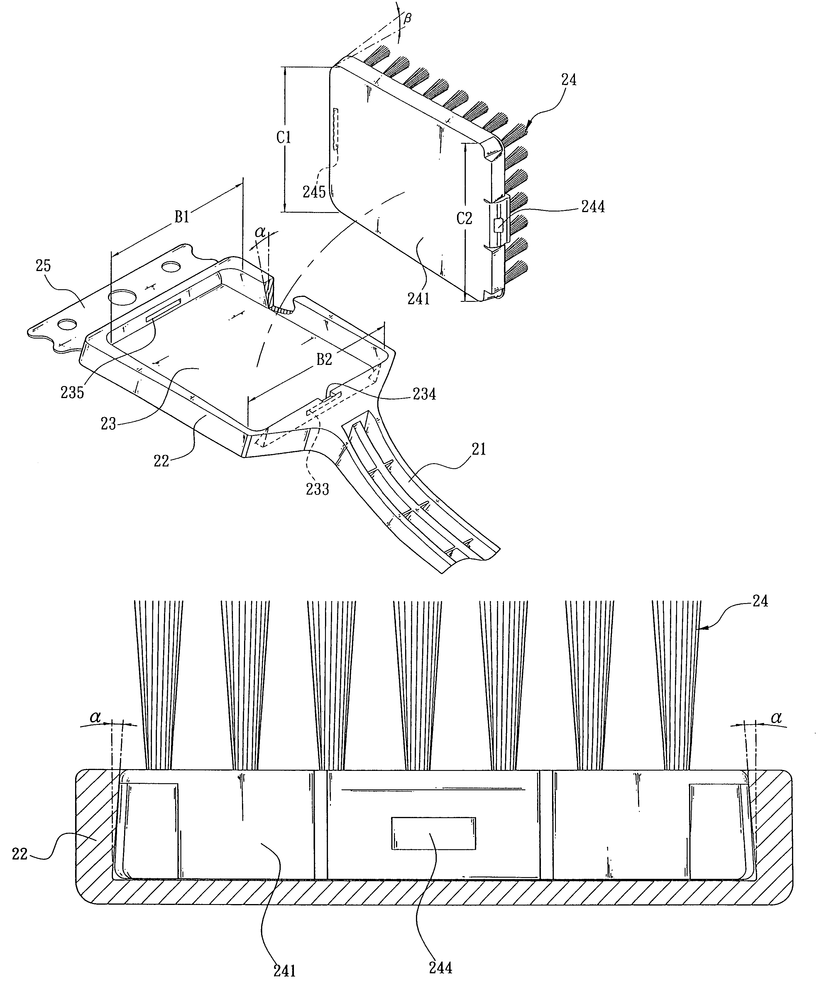
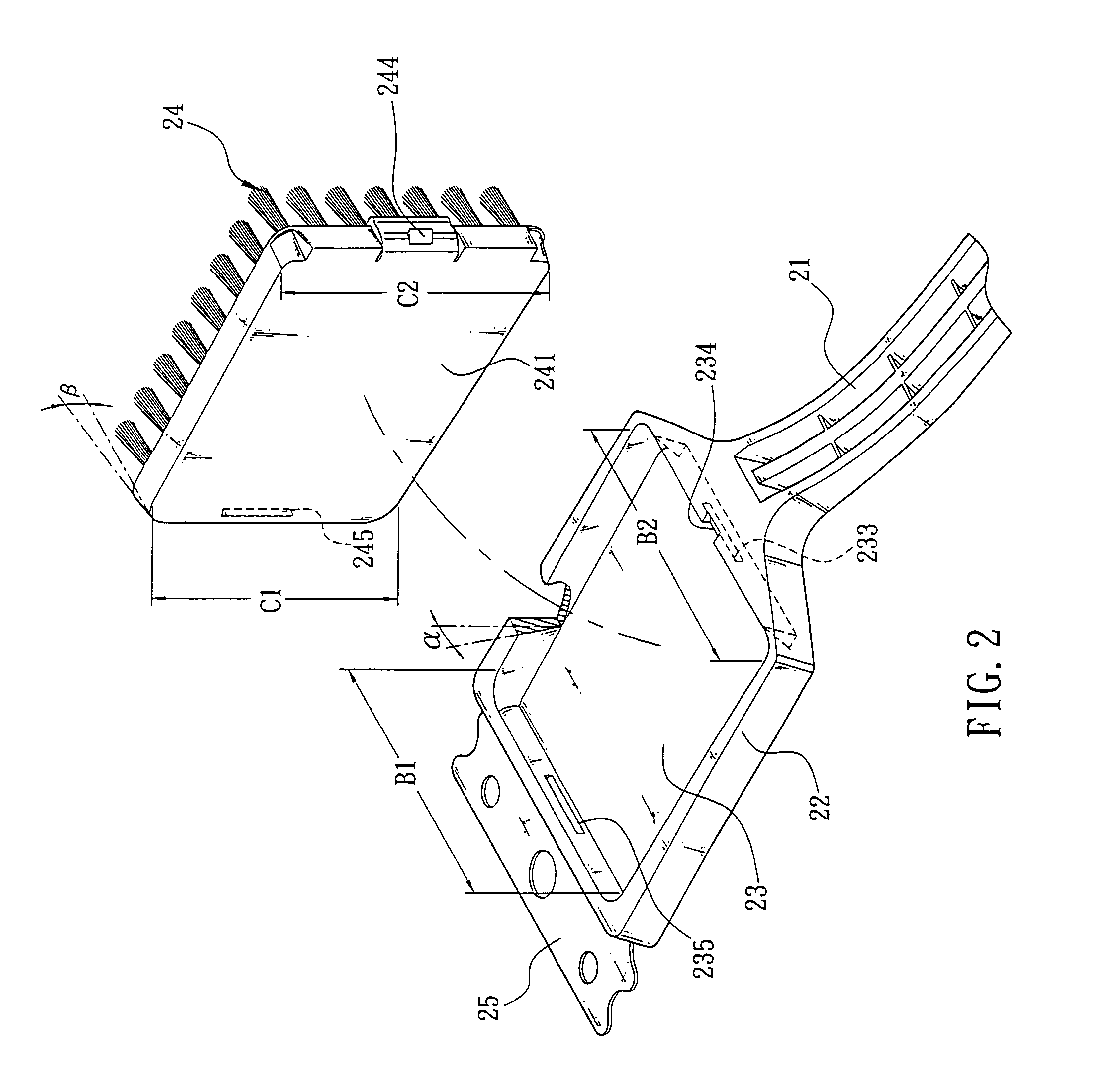
[0018]Please refer to FIGS. 2, 3 and 4 for a cleaning brush structure with a replaceable brush hair plate of the present invention. The cleaning brush 20 comprises a slender rod body 21, a plate member 22 extended from one end of the slender rod body 21 and an accommodating groove 23 disposed on one side of the plate member 22, wherein the accommodating groove 23 is tapered in width from a rear end B2 to a corresponding front end B1 such that the internal walls on two opposite sides at the positions adjacent to the front end B1 slightly face a bottom surface inside the accommodating groove 23 to define an opening above the accommodating groove 23. The two internal walls are inclined to slightly face the bottom of the accommodating groove 23 at an angle of inclination α that increases from the rear end B2 to the front end B1. Therefore, the opening at the front end B1 is slightly smaller than the bottom as shown in FIGS. 2 and 3. A first latch groove 233 is disposed in a wall at the ...


PUM


Abstract

The present invention discloses a cleaning brush structure having a replaceable brush hair plate, which comprises an accommodating groove being tapered in width from its front end to its rear end on a plate body of the cleaning brush and a baseboard being tapered in width from its front end to its rear end, such that the baseboard can be secured into the accommodating groove and will not fall out easily. Further, the accommodating groove has an opening disposed above the accommodating groove and slightly smaller than the bottom thereof, and its rear end is broader than its front end, such that when a user takes out the baseboard for replacement or cleaning, the baseboard will not come out uncontrollably due to the excessively applied force.

Description

FIELD OF THE INVENTION[0001]The present invention generally relates to cleaning brushes, more particularly to a cleaning brush structure having a replaceable brush hair plate.BACKGROUND OF THE INVENTION[0002]In the area of general cleaning accessories, a brush used for cleaning is very common to everyone, and one of these cleaning brushes will be described briefly below.[0003]Please refer to FIG. 1. A cleaning brush 10 comprises a slender rod body 11, a plate member 12 extended from one end of the slender rod body 11, a brush hair plate 14 integrally coupled onto the plate member 12 to form a brush hair plate.[0004]Further, the plate member 12 comprises a metal plate 15 protruded from the front of the plate member 12 for removing a tough dirt or stain. The brush hair plate 14 comprises a plurality of brush hairs or scrubbing cloths; and the embodiment as shown in FIG. 1 adopts a plurality of brush hairs. Further, the slender rod body 11 has a handle 16 at the other end to facilitate...

Claims


Application Information

Patent Timeline
Patent Type & Authority Patents(United States)
IPC IPC(8): A46B7/04
CPCA46B7/04
Inventor YU, SHU-FENG
Owner YU SHU FENG
Why Eureka
Try Eureka