Power-operated clutch actuator for torque transfer mechanisms

a technology of torque transfer mechanism and clutch actuator, which is applied in mechanical actuated clutches, transportation and packaging, and gearing

Inactive Publication Date: 2006-09-26
MAGNA POWERTRIAN INC (US)
View PDF36 Cites 63 Cited by
  • Summary
  • Abstract
  • Description
  • Claims
  • Application Information

AI Technical Summary

Problems solved by technology

For example, the size and weight of the friction clutch components and the electrical power and actuation time requirements for the clutch actuator that are needed to provide the large clutch engagement loads may make such system cost prohibitive in some motor vehicle applications.

Method used


Image

  • Power-operated clutch actuator for torque transfer mechanisms
  • Power-operated clutch actuator for torque transfer mechanisms
  • Power-operated clutch actuator for torque transfer mechanisms

Examples


Embodiment Construction

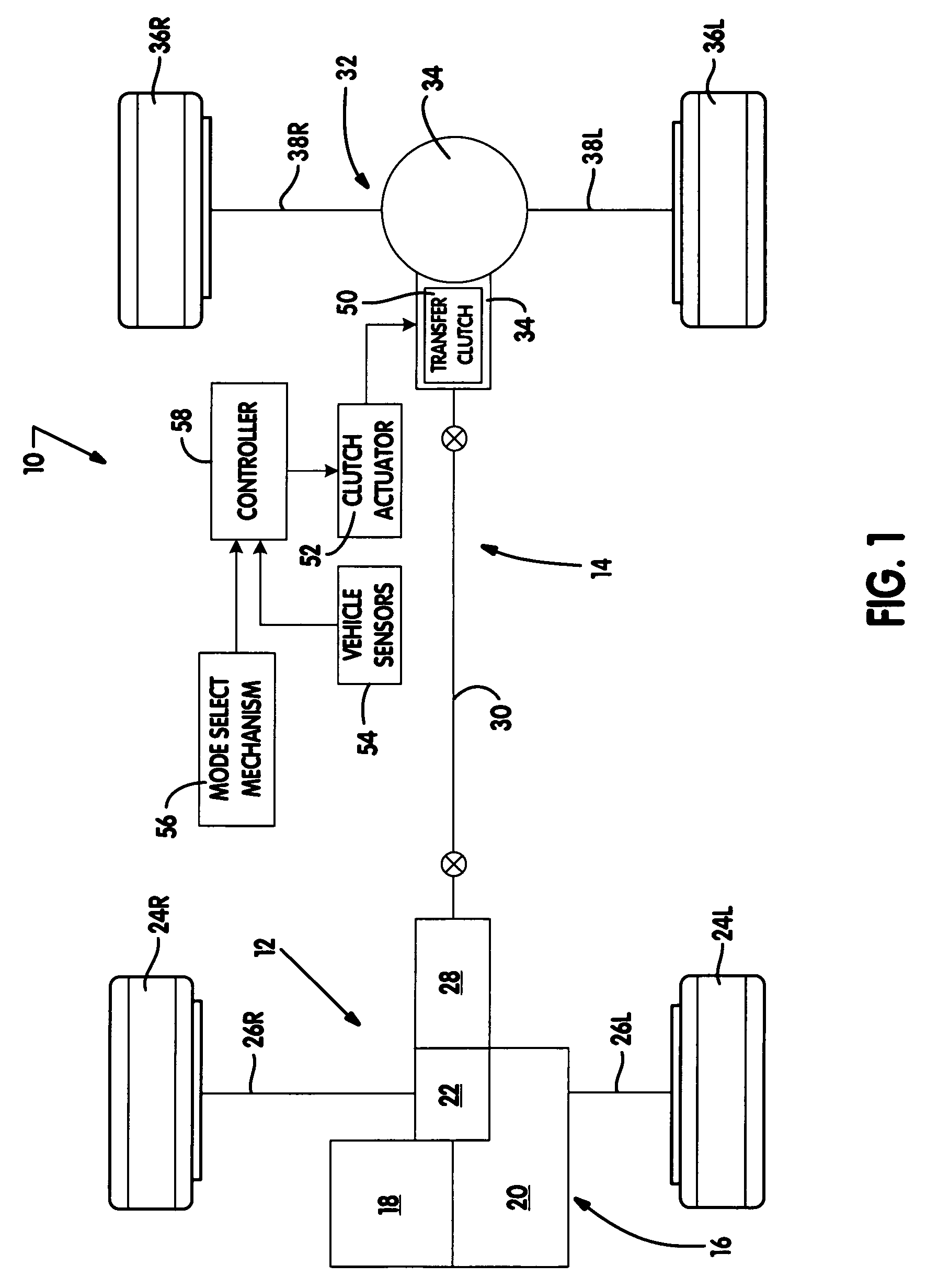
[0021]The present invention is directed to a torque transfer mechanism that can be adaptively controlled for modulating the torque transferred between a first rotary member and a second rotary member. The torque transfer mechanism finds particular application in power transmission devices for use in motor vehicle drivelines such as, for example, an on-demand transfer clutch in a transfer case or an in-line torque coupling or a biasing clutch associated with a differential unit in a transfer case or a drive axle assembly. Thus, while the present invention is hereinafter described in association with particular arrangements for use in specific driveline applications, it will be understood that the arrangements shown and described are merely intended to illustrate embodiments of the present invention.

[0022]With particular reference to FIG. 1 of the drawings, a drivetrain 10 for an all-wheel drive vehicle is shown. Drivetrain 10 includes a primary driveline 12, a secondary driveline 14,...


PUM


Abstract

A torque transfer mechanism is provided for controlling the magnitude of a clutch engagement force exerted on a multi-plate clutch assembly that is operably disposed between a first rotary and a second rotary member. The torque transfer mechanism includes a power-operated face gear clutch actuator for generating and applying a clutch engagement force on the clutch assembly.

Description

CROSS-REFERENCE TO RELATED APPLICATIONS[0001]This application claims the benefit of U.S. Provisional Application No. 60 / 647,331, filed on Jan. 26, 2005. The disclosure of the above application is incorporated herein by reference.FIELD OF THE INVENTION[0002]The present invention relates generally to power transfer systems for controlling the distribution of drive torque between the front and rear drivelines of a four-wheel drive vehicle and / or the left and right wheel of an axle assembly. More particularly, the present invention is directed to a power transmission device for use in motor vehicle driveline applications having a torque transfer mechanism equipped with a power-operated clutch actuator that is operable for controlling actuation of a multi-plate friction clutch assembly.BACKGROUND OF THE INVENTION[0003]In view of increased demand for four-wheel drive vehicles, a plethora of power transfer systems are currently being developed for incorporation into vehicular driveline app...

Claims


Application Information

Patent Timeline
Patent Type & Authority Patents(United States)
IPC IPC(8): F16D21/04F16D27/00
CPCB60K23/0808F16D28/00F16D27/004F16D2500/50858F16D2500/1025F16D21/04F16D27/00
Inventor EKONEN, TODDBRADLEY, DOUGLAS
Owner MAGNA POWERTRIAN INC (US)
Why Eureka
Try Eureka