Conveying unit with container accumulation

a technology of conveying unit and container, which is applied in the direction of mechanical conveyors, conveyors, storage devices, etc., can solve the problems of container accumulation, integration of these containers, and no longer inserting itself into the preferred axial flow, and achieves the effect of simple and reliable means

Inactive Publication Date: 2006-09-26
SIDEL PARTICIPATIONS SAS
View PDF10 Cites 2 Cited by
  • Summary
  • Abstract
  • Description
  • Claims
  • Application Information

AI Technical Summary

Benefits of technology

[0018]The object of this invention is to alleviate these problems by suggesting a conveying unit with accumulation of containers, especially of bottles, allowing easy detours of these bottles located near the sides to the main flow, with implementation by simple and reliable means.

Problems solved by technology

This results in an accumulation of containers for forming a buffer inventory.
It has been found that these preferred flows that are formed more or less systematically in the extension of a feed conveyor are the result of incorrect distribution of the containers on the table, more especially in the accumulation phase.
This results in that these containers that are located on a feed conveyor, following a lateral direction, very easily push back the containers that are located on the accumulation conveyors and, due to the fact that they are advancing more quickly, they prevent integration of these containers located on the feed conveyors into the preferred flux that has been formed in this way.
Such a container is exposed to thrusts following the aforementioned 30° angles relative to the longitudinal axis of the table, such that it has a tendency to be pushed back laterally and thus can no longer insert itself into the preferred axial flow.
This results in that the containers located on the accumulation conveyor or conveyors are naturally pushed downstream from the table without a preferred path for the containers located on the feed conveyor or conveyors being able to be set up.
These baffles in the form of a sawtooth tend to promote a blockage of the containers at the bottom of the teeth, however, which results in the necessary adaptation of these baffles to the diameter of the containers.
Moreover, providing such added baffles entails a relatively major expenditure of labor and accessories for fixing and adjusting them in position in order to achieve a correct sequence of detours of the containers individually and in order to route them into the main flow according to the predetermined arrangement in staggered rows.
Moreover, the very fact of adding these baffles entails additional risks of problems such as deformations or the like and thus the necessity of additional maintenance interventions.

Method used


Image

  • Conveying unit with container accumulation
  • Conveying unit with container accumulation
  • Conveying unit with container accumulation

Examples


Embodiment Construction

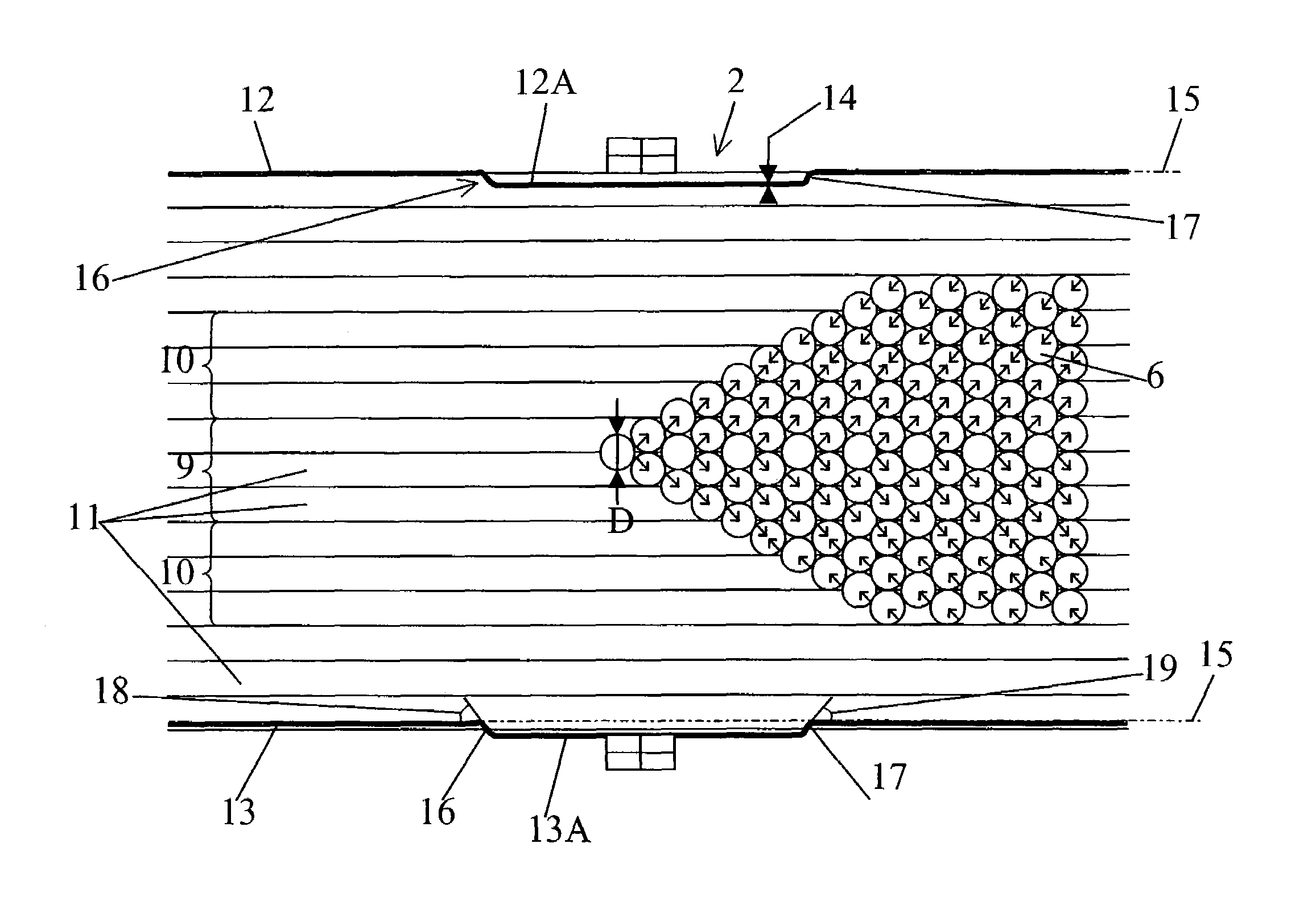
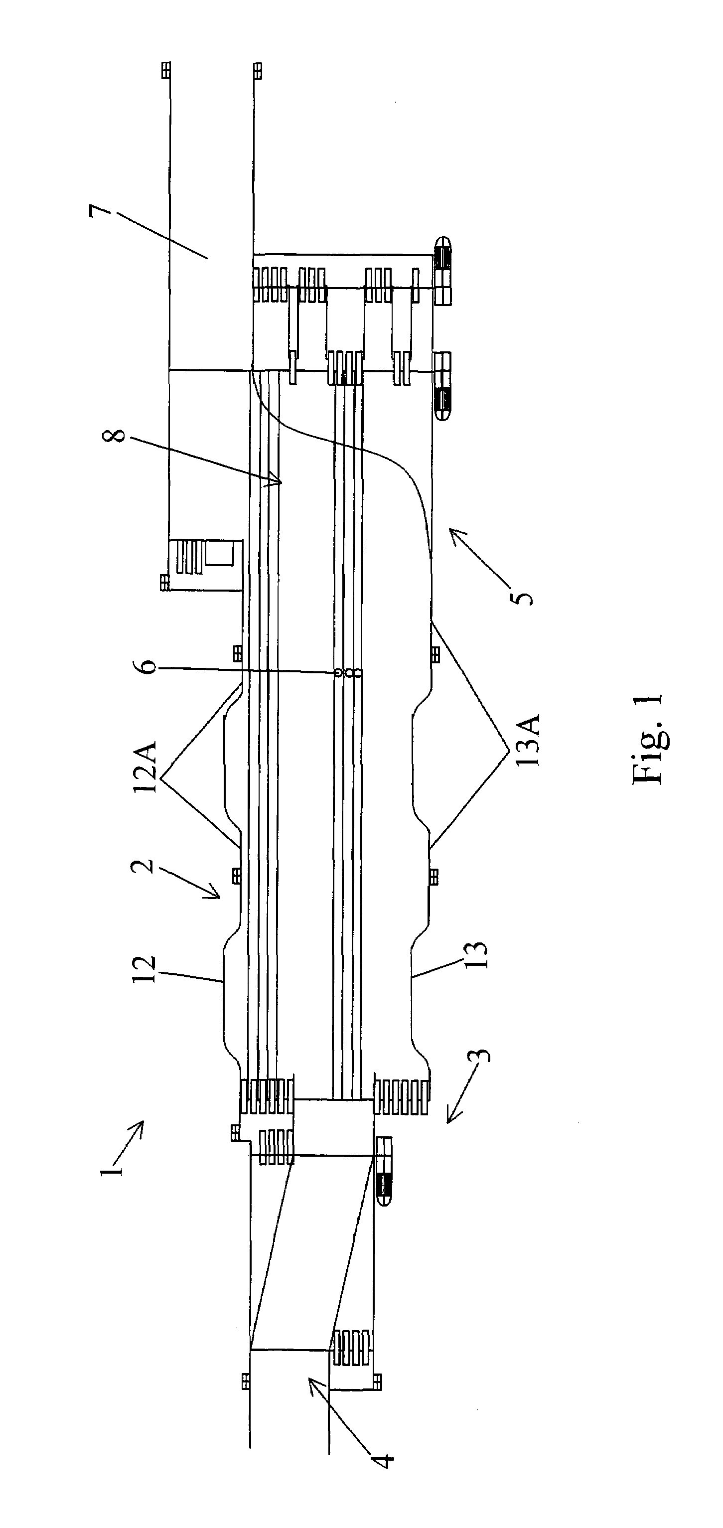
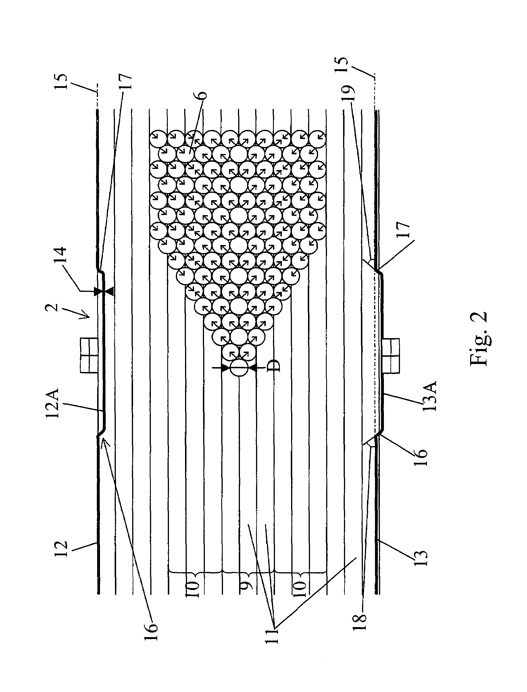
[0023]FIG. 1 of the attached drawings shows a conveying unit with accumulation of containers 6, especially of bottles, comprising an accumulation table 2 equipped laterally with guide rails 12, 13 that keep the containers 6 on said table 2, and composed of a juxtaposition of at least one feed conveyor 9 and one accumulation conveyor 10, the bottles 6 being routed onto this table 2 at its upstream end 3 especially via at least one feed transporter 4 and being discharged on the downstream end 5 via at least one discharge transporter 7, if necessary with implementation of a transition conveyor 8. The feed transporter 4 preferably discharges onto a feed conveyor 9 that advances at a speed greater than that of an accumulation conveyor 10.

[0024]As an example, the accumulation table 2 can be composed of a juxtaposition of several lines with pallets 11, of which certain ones form a feed conveyor 9 and others form an accumulation conveyor 10, the assignment of these lines with pallets being ...


PUM


Abstract

A conveying unit with accumulation of containers (6), especially of bottles, includes an accumulation table (2) equipped laterally with guide rails (12, 13) and composed of a juxtaposition of at least one feed conveyor (9) and one accumulation conveyor (10), the containers (6) being routed onto this table (2) at its upstream end via at least one feed transporter, and being discharged on the downstream end via at least one discharge transporter. The unit is characterized in that at least one of the guide rails (12, 13) is equipped with a transverse offset (12a, 13a), composed of a segment of the guide rail (12, 13), with an amplitude (14) of between 0.2 and 0.8 times the diameter D of a container (6) and offset relative to the longitudinal axis (15) of the guide rail (12, 13) by a distance corresponding to the amplitude (14).

Description

FIELD OF THE INVENTION[0001]This invention relates to the field of conveying containers, especially bottles, and the object is a conveying unit with accumulation of containers, especially of bottles, comprising an accumulation table equipped laterally with guide rails and composed of a juxtaposition of at least one feed conveyor and one accumulation conveyor. The bottles are routed onto this table, at its upstream end, especially via at least one feed transporter, and are discharged on the downstream end via a discharge transporter.BACKGROUND OF THE INVENTION[0002]In a packaging line for containers of any product, said containers pass through various treatment-stations. Thus, in the particular case of a bottling unit, it is common to have the containers, especially if they are in the form of bottles, pass through a washing unit, under a bottler, then to a labeller and optionally to a packager.[0003]Between these different treatment stations, these containers are moved by transporter...

Claims


Application Information

Patent Timeline
Patent Type & Authority Patents(United States)
IPC IPC(8): B65G47/68
CPCB65G47/5104B65G47/682B65G2201/0252B65G2201/0244
Inventor PETROVIC, ZMAJ
Owner SIDEL PARTICIPATIONS SAS
Why Eureka
Try Eureka