Arrangement and method in electric filter

a technology of arrangement and method, applied in the direction of electric supply techniques, combustion process, combustion treatment, etc., can solve the problems of cost increase of warm air scavenging, and achieve the effect of simple and reliable means

Active Publication Date: 2015-11-12
VALMET TECH OY
View PDF15 Cites 0 Cited by
  • Summary
  • Abstract
  • Description
  • Claims
  • Application Information

AI Technical Summary

Benefits of technology

[0009]The insulator chamber of the electric filter is connected through the first scavenging duct to a channel conveying process gas in the boiler plant, which means that process gas can be supplied to the insulator chamber. The advantage is that the scavenging gas of the insulator chamber need not be separately heated.
[0010]The idea of an embodiment is that the process gas is secondary, tertiary or some other corresponding air of the boiler plant. The advantage is that at least one of the above-mentioned airs is at a temperature suitable for scavenging gas.
[0011]The idea of an embodiment is that the temperature of the process gas is in the range of 80 to 300° C. The advantage is that process gas need not be heated before it is fed into the insulator chamber.
[0012]The idea of an embodiment is that the arrangement comprises a heating device and a second scavenging duct that is connected between the heating device and insulator chamber, whereby the gas heated with the heating device can be conveyed to the insulator chamber as scavenging gas, and the second scavenging duct is connected to the insulator chamber through a valve arrangement arranged to open and close it. The advantage is that it is possible to supply gas heated with the heating device to the insulator chamber during the start-up phase of the boiler plant or some other phase when the boiler plant cannot provide suitably heated scavenging gas.
[0013]The idea of an embodiment is that the valve arrangement comprises a three-way valve which is arranged in the first scavenging duct with its third connection connected to a second scavenging duct, and the valve arrangement comprises control means for controlling said three-way valve and for changing the scavenging gas supply from the first scavenging duct to the second scavenging duct and vice versa. The advantage is that the source of the scavenging gas can be changed with simple and reliable means.

Problems solved by technology

As the price of electricity increases, the costs of warm air scavenging have become a problem.

Method used


Image

  • Arrangement and method in electric filter
  • Arrangement and method in electric filter

Examples


Embodiment Construction

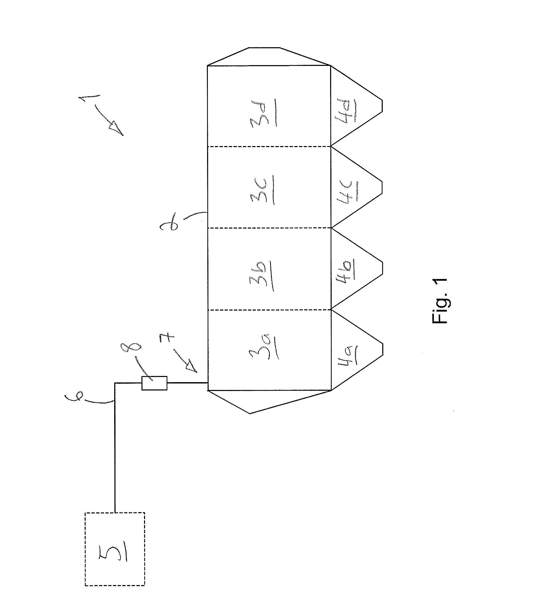
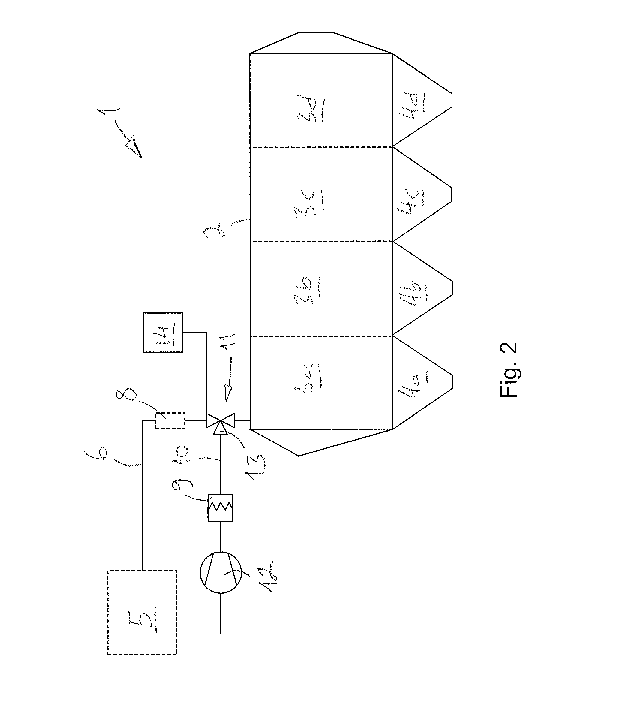
[0019]FIG. 1 is a schematic view of an arrangement and method.

[0020]An electric filter 1 known per se comprises an insulator chamber 2, which in this case is divided into four fields 3a, 3b, 3c, 3d. Each field 3a to 3d has a bottom funnel 4a to 4d, through which solid matter removed from the flue gases is removed from the insulator chambers 2.

[0021]The electric filter 1 comprises numerous components and elements, such as electric isolators, supports, shakers, pressure transmitters that are not shown in the figures to simplify the presentation.

[0022]The task of the electric filter 1 is to purify the flue and product gases created as a result of a thermal process. In this context, the thermal process refers to the processing of fuel in a boiler plant by combustion, gasification or pyrolysis, for instance.

[0023]The boiler plant 5 may comprise one or more soda recovery boilers, bubbling fluidised-bed boilers (BFB), circulating fluidised-bed boilers (CFB), gas plants, pyrolysis plants, g...


PUM


Abstract

An arrangement and method in connection with an electric filter of a boiler plant, the electric filter comprising an insulator chamber. The arrangement comprises a first scavenging duct for conveying warm scavenging gas to the insulator chamber. Said first scavenging duct is connected to a channel conveying process gas in the boiler plant, which means that it is possible to supply process gas to the insulator chamber.

Description

BACKGROUND[0001]The invention relates to an arrangement in connection with an electric filter of a boiler plant, the electric filter comprising an insulator chamber and a first scavenging duct for conveying warm scavenging gas to the insulator chamber.[0002]The invention further relates to a method in connection with an electric filter of a boiler plant, the electric filter comprising an insulator chamber and a first scavenging duct for conveying warm scavenging gas to the insulator chamber.[0003]Electric filters are used, among other things, in removing particles from flue gases.[0004]In the insulator chambers of electric filters, warm air scavenging is used as sealing air to protect electric insulators from dust and condensate. Scavenging air is heated with an electric heater to the required temperature that is 140° C., for example.[0005]As the price of electricity increases, the costs of warm air scavenging have become a problem.BRIEF DESCRIPTION[0006]The arrangement and method o...

Claims


Application Information

Patent Timeline
Patent Type & Authority Applications(United States)
IPC IPC(8): F23J15/02B03C3/80B03C3/70
CPCF23J15/025B03C3/80B03C3/70F23J2217/102B03C3/017B03C3/34F23J15/00
Inventor TOLVANEN, JUHA
Owner VALMET TECH OY
Why Eureka
Try Eureka