Arrangement for protecting equipment of a power system

a technology for protecting equipment and power systems, applied in the direction of mechanical power/torque control, dc source parallel operation, amplifier modification to reduce noise influence, etc., can solve the problems of power swings so severe, weak real and reactive power oscillation, and loss of synchronism between different parts of the system. achieve the effect of simple and reliable means

Active Publication Date: 2012-12-25
HITACHI ENERGY LTD
View PDF16 Cites 2 Cited by
  • Summary
  • Abstract
  • Description
  • Claims
  • Application Information

AI Technical Summary

Benefits of technology

[0015]Thus, the present invention is based on the new approach to use results of frequency measurements of current and voltage at at least one location in the electrical power system along the interconnection between said two theoretical electrical machines for determining where a potential pole slip electrical center is located. This determination of the location of the potential pole slip electrical center will not be dependent upon any estimation of impedances of the electrical power system and will be very reliable. Furthermore, it may by this way of proceeding very early be determined where measures as isolation of equipment shall later on be taken would a pole slip occur and start of control procedures for obtaining recovery of any unbalances may start early for, when possible, avoiding isolation or tripping of equipment of the electrical power system.
[0017]According to another embodiment of the invention said fourth means is configured to, upon determination of occurrence of a said power swing, determine that said location is located on a motor side of said potential pole slip electrical center in said two machine system if the frequency of the current measured by said first means is higher than the frequency of the voltage at said location and determine that said location is located on a generator side of said potential pole slip electrical center is located on a motor side of said location in said two machine system if the frequency of the current measured by said first means is lower than the frequency of the voltage at said location. It may by very simple and reliable means by use of the result of these frequency measurements be decided on which side of a potential pole slip electrical center a said measuring location is located, so that appropriate actions may be taken for protecting the electrical power system.

Problems solved by technology

However, in a non-recoverable situation, the power swings become so severe that the synchronism is lost between different parts of the system, such as generators thereof, which is a condition referred to as pole slipping or out-of-step in the literature.
In the case of a pole slip the excitation of electrical machines of the power system is generally intact, but there are strong oscillations of real and reactive power due to different rotational speed of involved machine rotors.
Apart from the electrical phenomena, oscillations of mechanical masses also expose generators and / or other equipment of the power system to considerable pulsating mechanical stresses.
Even though modern electrical power systems are designed and operate with high degree of security against power swings and even more against pole slipping, these two phenomena may occur especially during abnormal system conditions.
If a pole slip is allowed to persist in one part of a power system then other electrical machines / equipment may follow and we do not only have an immediate risk of damaging bearings of rotors and other mechanical parts, but the stability of a complete electrical power system may be lost and complete blackout of the power system may be the final outcome.
In the case of severe faults it may be absolutely necessary to isolate a part of the electrical power system from the rest thereof, but it is also of importance to be able to determine whether a power swing is recoverable or not, since false tripping of such a protecting arrangement must be avoided, since that would result in a waste of considerable costs.
However, this theory is based upon a rather rough estimation of impedances of the electrical power systems.

Method used


Image

  • Arrangement for protecting equipment of a power system
  • Arrangement for protecting equipment of a power system
  • Arrangement for protecting equipment of a power system

Examples


first embodiment

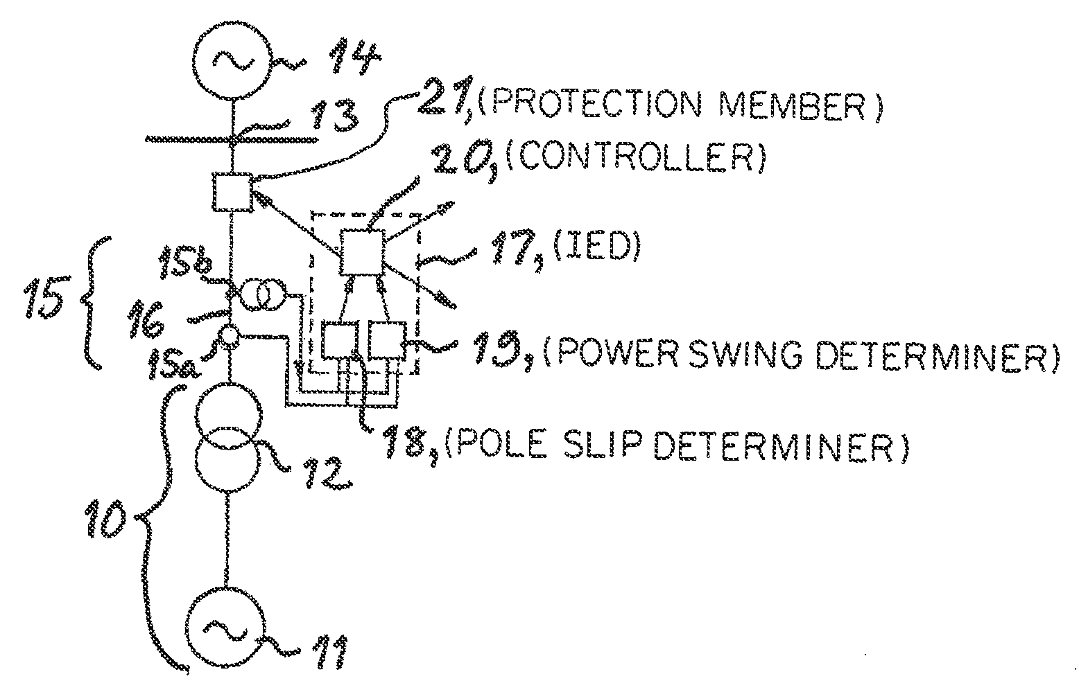
[0046]An arrangement according to the invention is very schematically illustrated in FIG. 8. This arrangement is configured to protect an electrical power system having a block 10 of a generator 11 and a transformer 12 connected through a high voltage station 13 to a high voltage system 14 for transmitting electric power. This high voltage system 14 may be considered as an electrical machine with infinite power in an equivalent two machine system. The arrangement has first means 15 located in the interconnection between the generator / transformer block 10 and the high voltage station 13 and configured to measure the frequency of the current (15a) and voltage (15b) at this location 16. The arrangement further comprises a relay in the form of an Intelligent Electronic Device IED 17 including second means (or pole slip determiner) 18 receiving values of frequency of the current and the voltage measured and configured to, while considering the electrical power system as an equivalent two...

second embodiment

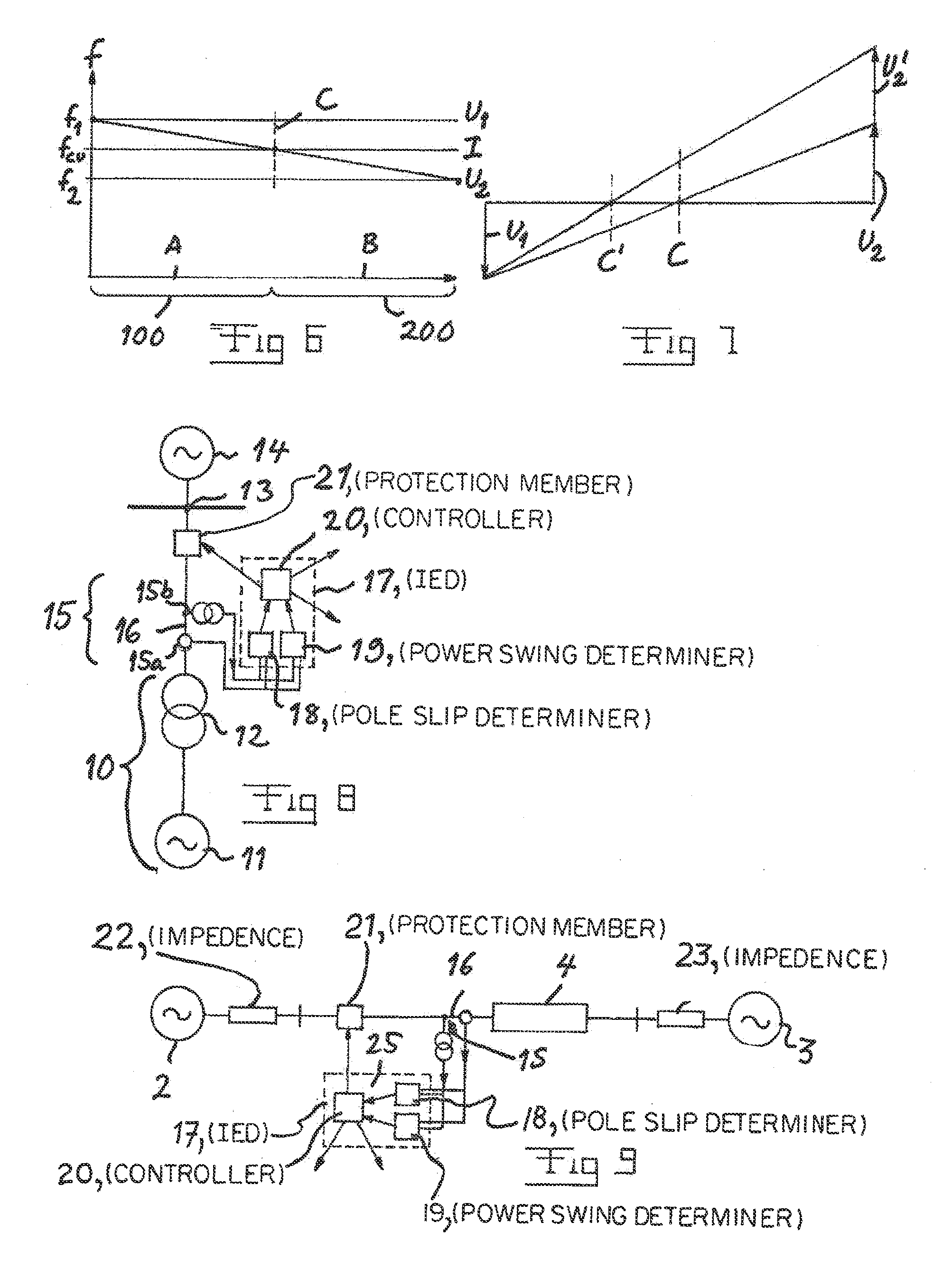
[0047]FIG. 9 illustrates an arrangement according to the invention configured to protect an electrical power system in the form a main electrical power system including a first 2 and a second 3 electrical power system and an interconnection 4 therebetween. The parts of the arrangement according to this embodiment corresponding to parts of the embodiment shown in FIG. 8 are here provided with the same reference numerals. The interconnection is here represented by an impedance. Thus, the two power systems and the interconnection form a radial link, so that the two machine theory is fully applicable. Said first means 15 is configured to measure the frequency of current and voltage at a location 16 on one side of the interconnection 4. Furthermore, the arrangement comprises a device 25 configured to use values of the frequency of current and voltage measured and based upon information of properties of the interconnection stored in a memory carry out a calculation while using any of diff...

third embodiment

[0048]FIG. 10 illustrates an electrical power system, the Swedish power system, in the form of a meshed electrical power network 30, and an arrangement according to the invention is configured to protect this meshed electrical power network by selecting two locations 31, 32 for measuring the frequency of the current and voltage by first means 34, 35 so that these measurements will be carried out in the same power flow corridor within the network enabling said second means to consider said meshed electrical power network as an equivalent two machine system as shown in FIG. 11. Accordingly, the system shown in FIG. 11 only differs from that shown in FIG. 9 by the fact that measurements are here carried out at two different locations, namely at each end of the interconnection. This means that it is not necessary to be aware of the value of any impedances of said interconnection or of the two sources, but it may be relied only upon said frequency measurements for determining in which pa...


PUM


Abstract

An arrangement for protecting equipment of an AC electrical power system comprises first means configured to measure the frequency of the current and voltage at at least one location in the electrical power system along an interconnection between two theoretical electric machines of an equivalent two machine system. Fourth means are configured to use the values of the frequency of the current and voltage measured to determine whether a power swing has occurred and if an occurrence of a power swing has been determined determine whether the measuring location is located on a motor side or a generator side of a potential pole slip electrical centre along said interconnection, the electrical centre being defined as the location where the voltage becomes zero during a pole slip, and send this information further to third means for use in a control for protecting equipment of the electrical power system.

Description

CROSS-REFERENCE TO RELATED APPLICATIONS[0001]The present application is a continuation of pending International patent application PCT / EP2009 / 057350 filed on Jun. 15, 2009 which designates the United States and the content of which is incorporated herein by reference.FIELD OF THE INVENTION[0002]The present invention relates to an arrangement for protecting equipment of an AC electrical power system.BACKGROUND OF THE INVENTION[0003]Protection of AC electrical power systems of any conceivable type is comprised, and such a system does typically, but not necessarily, among others include generators of electric power, transformers, converters and networks for transmitting electric power. Furthermore, the present invention is not restricted to any particular levels of electrical powers, voltages or currents of such electrical power systems.[0004]Sudden events in such an electrical power system, such as large jumps in load, fault occurrence or slow fault clearance, which disturb the balanc...

Claims


Application Information

Patent Timeline
Patent Type & Authority Patents(United States)
IPC IPC(8): G01R31/08G06F17/40G06F19/00
CPCH02J3/14H02J13/0017Y04S40/12Y02B90/2607Y04S20/222Y02B70/3225H02J2310/14H02J13/00004H02J13/00006Y02B90/20Y04S20/242Y02B70/30
Inventor GAJIC, ZORAN
Owner HITACHI ENERGY LTD
Why Eureka
Try Eureka