Exhaust system

Active Publication Date: 2013-07-04
EBARA CORP
View PDF19 Cites 18 Cited by
  • Summary
  • Abstract
  • Description
  • Claims
  • Application Information

AI Technical Summary

Benefits of technology

[0039]The present invention ...

Problems solved by technology

Further, the exhaust gases discharged from the process chamber contain a gas such as SiH4 at high risk of combustion and explo...

Method used


Image

  • Exhaust system
  • Exhaust system
  • Exhaust system

Examples


Embodiment Construction

[0048]An exhaust system according to embodiments of the present invention will be described in detail with reference to FIGS. 1 through 5. The same or corresponding members or elements having the same operation or function are denoted by the same reference numerals throughout views.

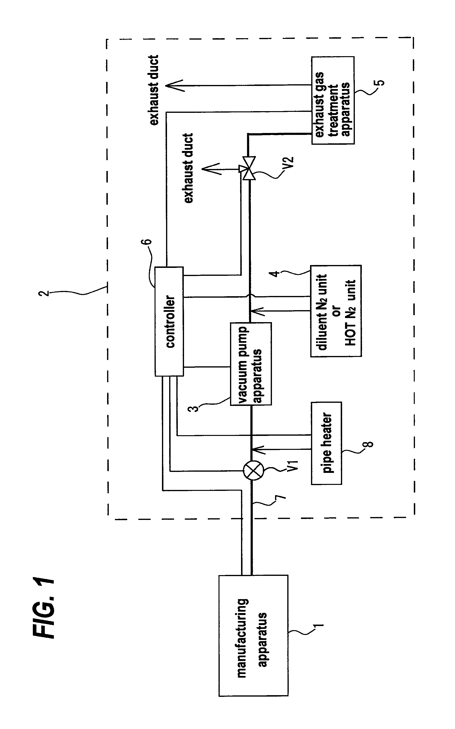
[0049]FIG. 1 is a schematic view showing a fundamental structure of the exhaust system according to the present invention. In FIG. 1, as an example of a manufacturing apparatus, a CVD apparatus in a semiconductor manufacturing apparatus will be described.

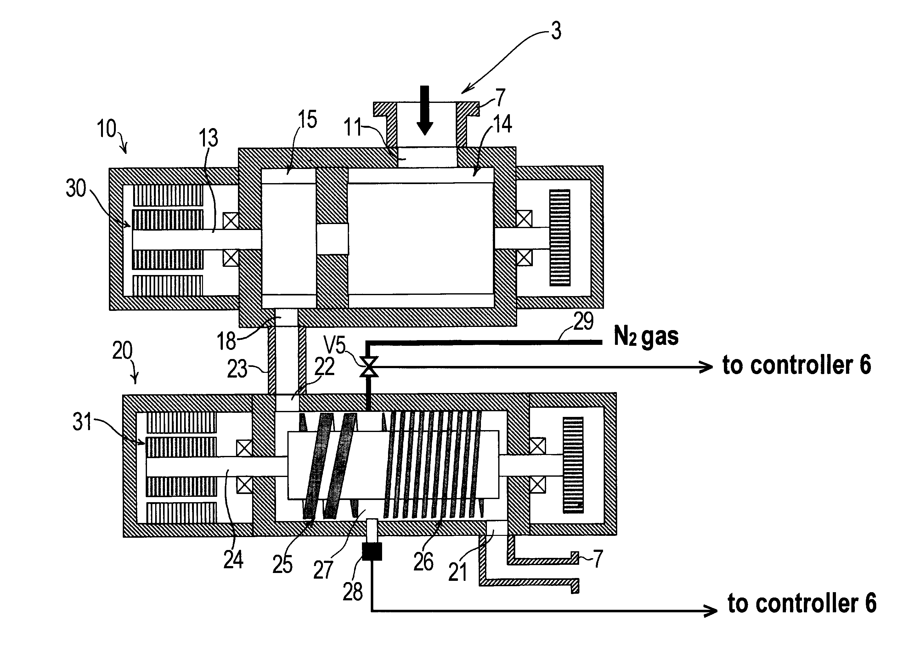
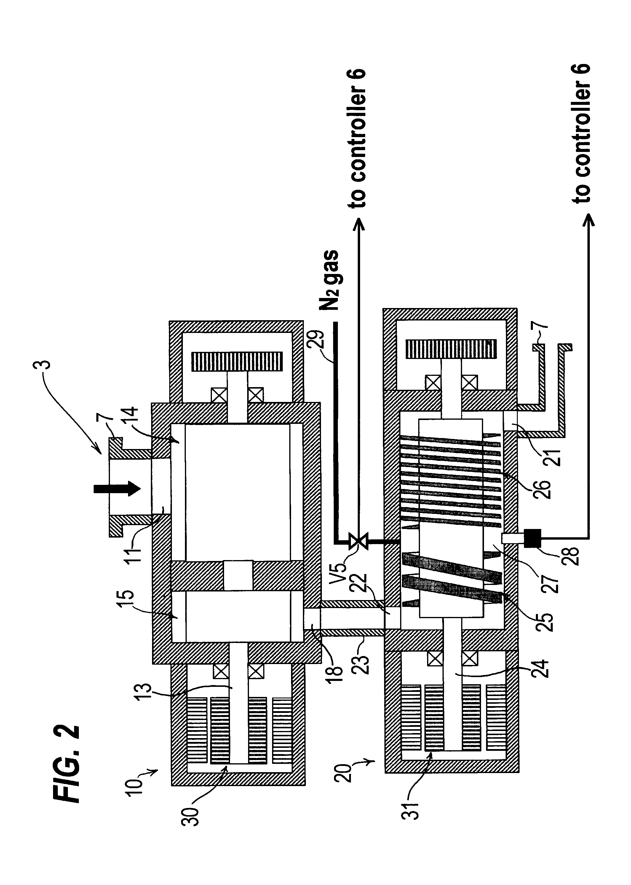
[0050]As shown in FIG. 1, the manufacturing apparatus 1 is connected to an exhaust system 2. The exhaust system 2 comprises a vacuum pump apparatus 3, a diluent N2 unit 4, an exhaust gas treatment apparatus 5, a controller 6, and connecting pipes 7 for connecting the manufacturing apparatus 1, the vacuum pump apparatus 3 and the exhaust gas treatment apparatus 5. In the case where the manufacturing apparatus 1 is a CVD apparatus, operational sequence in a...


PUM


Abstract

An exhaust system (2) is used for evacuating a chamber of a manufacturing apparatus (1) for manufacturing semiconductor devices, liquid crystal panels, LEDs, or solar cells. The exhaust system (2) includes a vacuum pump apparatus (3) for evacuating the chamber, an exhaust gas treatment apparatus (5) for treating an exhaust gas discharged from the chamber, and a controller (6) for controlling the vacuum pump apparatus (3) and/or the exhaust gas treatment apparatus (5). Information of operation process of the manufacturing apparatus (1), and the kind of gas and the flow rate of the gas supplied to the manufacturing apparatus (1) is inputted into the controller (6) to control the vacuum pump apparatus (3) and/or the exhaust gas treatment apparatus (5).

Description

TECHNICAL FIELD[0001]The present invention relates to an exhaust system in a manufacturing apparatus for manufacturing semiconductor devices, liquid crystal panels, LEDs, or the like, and more particularly to an exhaust system which has a vacuum pump for evacuating a chamber of the manufacturing apparatus, an exhaust gas treatment apparatus for treating an exhaust gas discharged from the chamber, and other apparatuses.BACKGROUND ART[0002]In a manufacturing process for manufacturing semiconductor devices, liquid crystal panels, LEDs, solar cells or the like, a process gas is introduced into a process chamber which is being evacuated to perform various processes such as an etching process, a CVD process or the like. The process chamber for performing several processes such as an etching process, a CVD process or the like is evacuated by a vacuum pump. Further, the process chamber and exhaust apparatuses connected to the process chamber are cleaned periodically by supplying a cleaning ...

Claims


Application Information

Patent Timeline
IPC IPC(8): F24F7/00
CPCB01D53/005B01D53/78F24F7/00F04B37/14F04B49/06B01D2258/0216F04B2201/1201H01L21/67253
Inventor SHINOHARA, TOYOJIKAWAMURA, KOHTARONAKAZAWA, TOSHIHARU
Owner EBARA CORP
Why Eureka
Try Eureka