Portable radial projection light source arrangement

a technology of radial projection and light source, which is applied in the direction of lighting applications, ways, and power sources with built-in power, can solve the problems of affecting the user's or even his or her clothes, and affecting the visibility of flares

Inactive Publication Date: 2006-09-26
COMAN PERRY
View PDF15 Cites 25 Cited by
  • Summary
  • Abstract
  • Description
  • Claims
  • Application Information

AI Technical Summary

Benefits of technology

[0008]A main object of the present invention is to provide a portable radial projection light source arrangement, wherein the light is radially projected from a light source to outside and is visible from great distances so that the portable radial projection light source arrangement functions as a road flare for quick use in an emergency.
[0009]Another object of the present invention is to provide a portable radial projection light source arrangement, wherein a reflecting member is positioned above the light source so that the light emitted from the light source is reflected by the reflecting member to radially project to outside. Therefore, the light is concentrated in a radial direction to highly enhance the visibility of the light source arrangement.
[0010]Another object of the present invention is to provide a portable radial projection light source arrangement, wherein the light source is powered by a replaceable battery to prolong the service life span thereof. In other words, the portable radial projection light source arrangement is re-usable so as to minimize the cost of the present invention.

Problems solved by technology

However, such conventional flare has several drawbacks.
Since the flare must be held by a user, such as a policeman, while burning and dropped on the roadway to form the temporary divider, there is a possibility of a burn to the user or even his or her clothes while the user holds the burning flare.
In addition, the flare may damage the surface of the roadway when the flare is placed thereon since the heat produced by the flare may melt or scar the roadway and the residue of the flare will remain on the roadway when the flare is used.
Therefore, the light projecting upwardly from the flare cannot enhance the visibility of the flare.
Thus, since the flare, it is a waste of energy since the flare produces not only light but also heat while burning.
As a result, the heat and the upward projecting light will minimize the effective of the flare.
Therefore, the time usage of the flare is not controlled by the user.

Method used


Image

  • Portable radial projection light source arrangement
  • Portable radial projection light source arrangement
  • Portable radial projection light source arrangement

Examples


Embodiment Construction

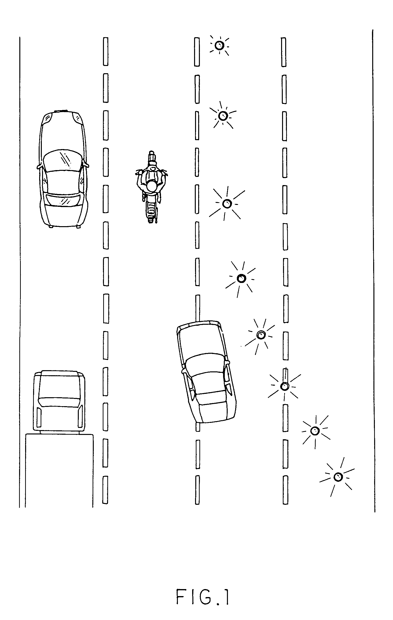
[0026]Referring to FIGS. 1 through 5 of the drawings, a portable radial projection light source arrangement according to a preferred embodiment of the present invention is illustrated, wherein the portable radial projection light source arrangement is capable of functioning as a road flare to form a temporary divider on a roadway, as shown in FIG. 1.

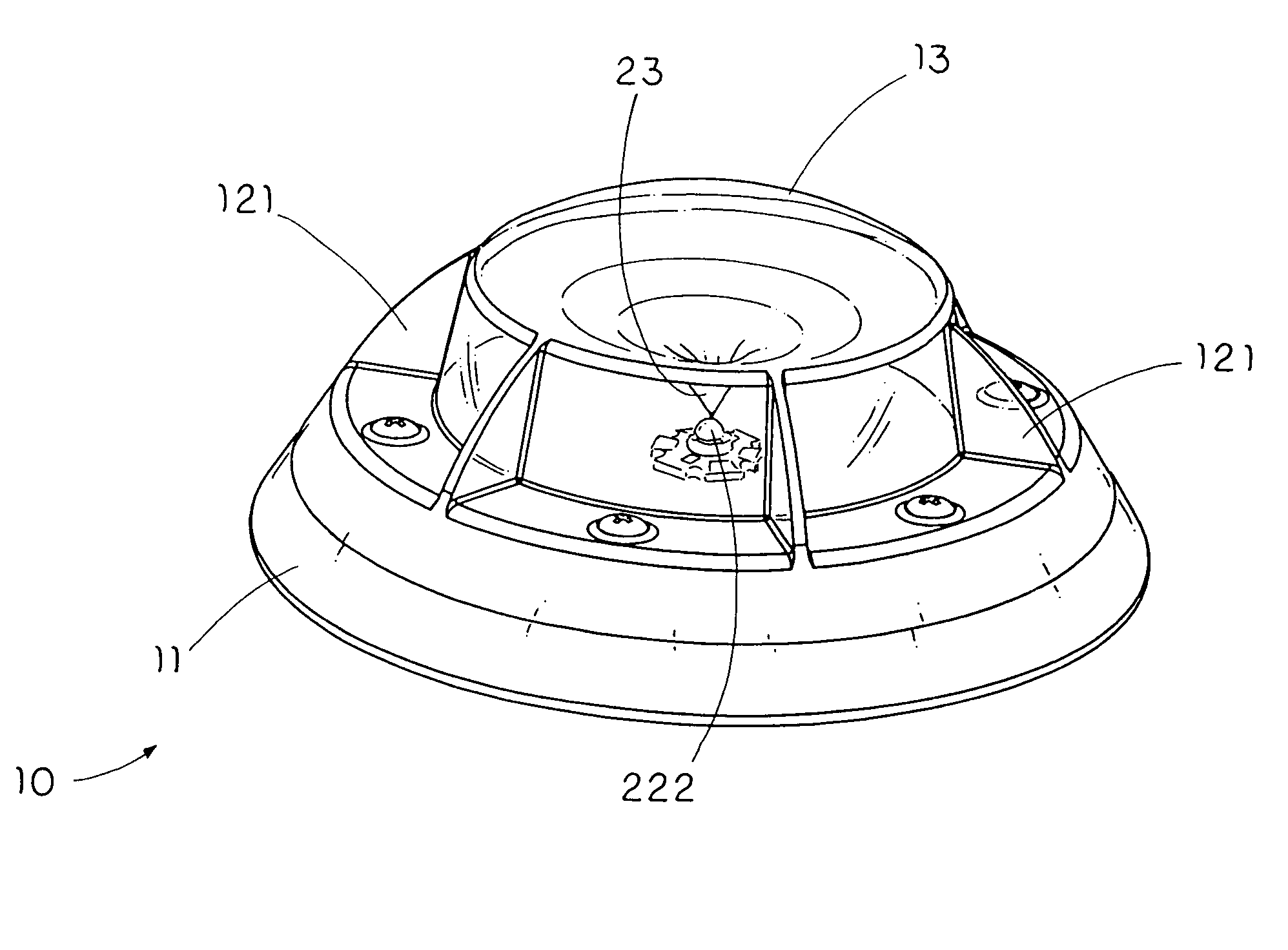
[0027]As shown in FIGS. 3 and 4, the portable radial projection light source arrangement comprises a shelter housing 10 and an illumination unit 20, wherein the shelter housing 10 comprises a protection base 11 having a light source cavity 111 therein, and a supporting frame 12 mounted on the protection base 11.

[0028]The illumination unit 20 comprises a power source 21 supported in the protection base 11, a light source 22 disposed in the light source cavity 111 and electrically connected to the power source 21, and a reflecting member 23 supported by the supporting frame 12 at a position coaxially above the light source 22 wherein the r...


PUM


Abstract

A portable radial projection light source arrangement includes a shelter housing and an illumination unit. The shelter housing includes a protection base having a light source cavity therein, and a supporting frame mounted on the protection base. The illumination unit includes a power source supported in the protection base, a light source disposed in the light source cavity and electrically connected to the power source, and a reflecting member supported at a position coaxially above the light source wherein the reflecting member has a light reflecting surface radially projected from the light source in such a manner that when the light source emits light, the light is radially reflected by the light reflecting surface of the reflecting member to outside.

Description

BACKGROUND OF THE PRESENT INVENTION[0001]1. Field of Invention[0002]The present invention relates to a light source arrangement, and more particularly to a portable radial projection light source arrangement, wherein the light is radially projected from a light source to outside and is visible from great distances so that the portable radial projection light source arrangement functions as a road flare for quick use in an emergency.[0003]2. Description of Related Arts[0004]At an incident, such as a traffic accident, an individual usually distributes a plurality of road flares on the road as a temporary divider on a roadway. In other words, the road flares alert other drivers that there is an accident in front so as to separate the accident from the roadway.[0005]Accordingly, one of the most common road flares is the ignition type disposable flare wherein the flare is simply ignited and directly disposed on the roadway. However, such conventional flare has several drawbacks. Since th...

Claims


Application Information

Patent Timeline
Patent Type & Authority Patents(United States)
IPC IPC(8): E01F9/00H03B1/00
CPCE01F9/065F21S9/022F21Y2101/02F21W2111/02F21W2111/00E01F9/559F21Y2115/10
Inventor COMAN, PERRY
Owner COMAN PERRY
Why Eureka
Try Eureka