Counter track joint with control angle reversal

a counter-track joint and control angle technology, applied in the direction of yielding couplings, mechanical equipment, rotary machine parts, etc., can solve the problems of joint jamming and joint control deterioration, and achieve good joint control conditions, high degree of efficiency, and long service life

Active Publication Date: 2006-09-26
GKN AUTOMOTIVE GMBH
View PDF8 Cites 20 Cited by
  • Summary
  • Abstract
  • Description
  • Claims
  • Application Information

AI Technical Summary

Benefits of technology

[0018]The primary advantages of the present design will once again be summarized below. The counter track principle of the joint in accordance with the invention achieves a long service life, even with large permanent angles of articulation within the operational articulation range, with a high degree of efficiency being ensured. The inventive tra

Problems solved by technology

The disadvantage of counter track joints, more particularly those wherein the track center lines of the first pairs of tracks are S-shaped, arises in the case of large articulation angles, w

Method used


Image

  • Counter track joint with control angle reversal
  • Counter track joint with control angle reversal
  • Counter track joint with control angle reversal

Examples


Embodiment Construction

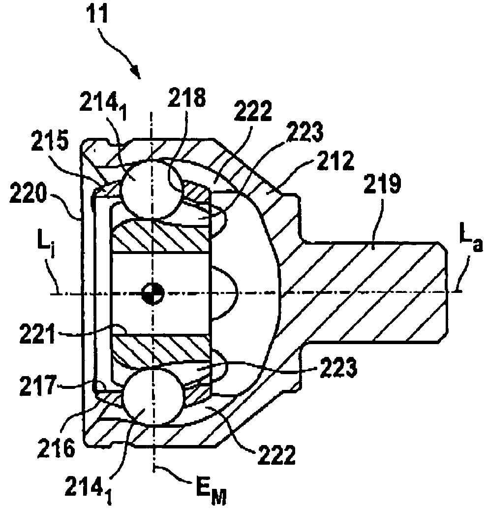
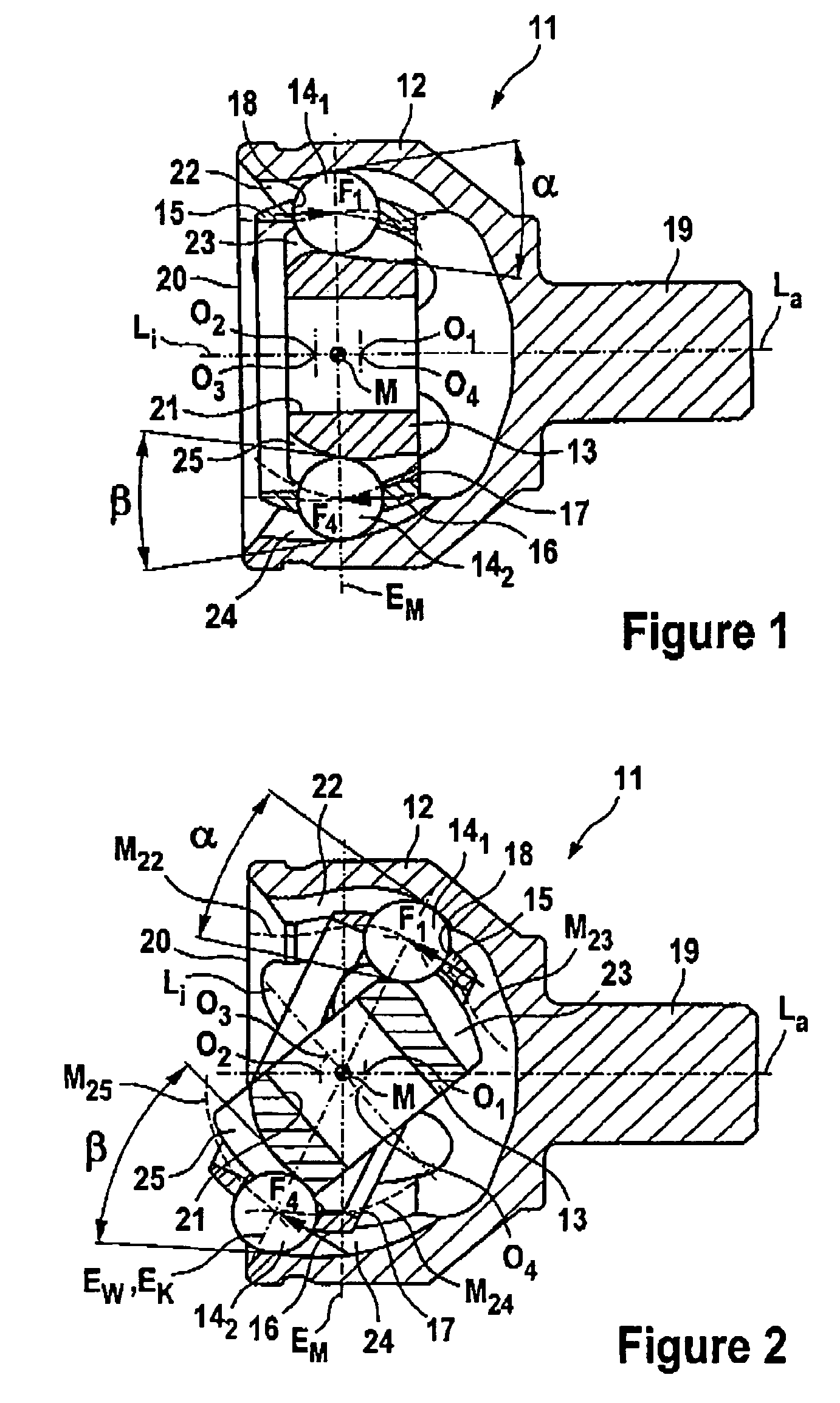
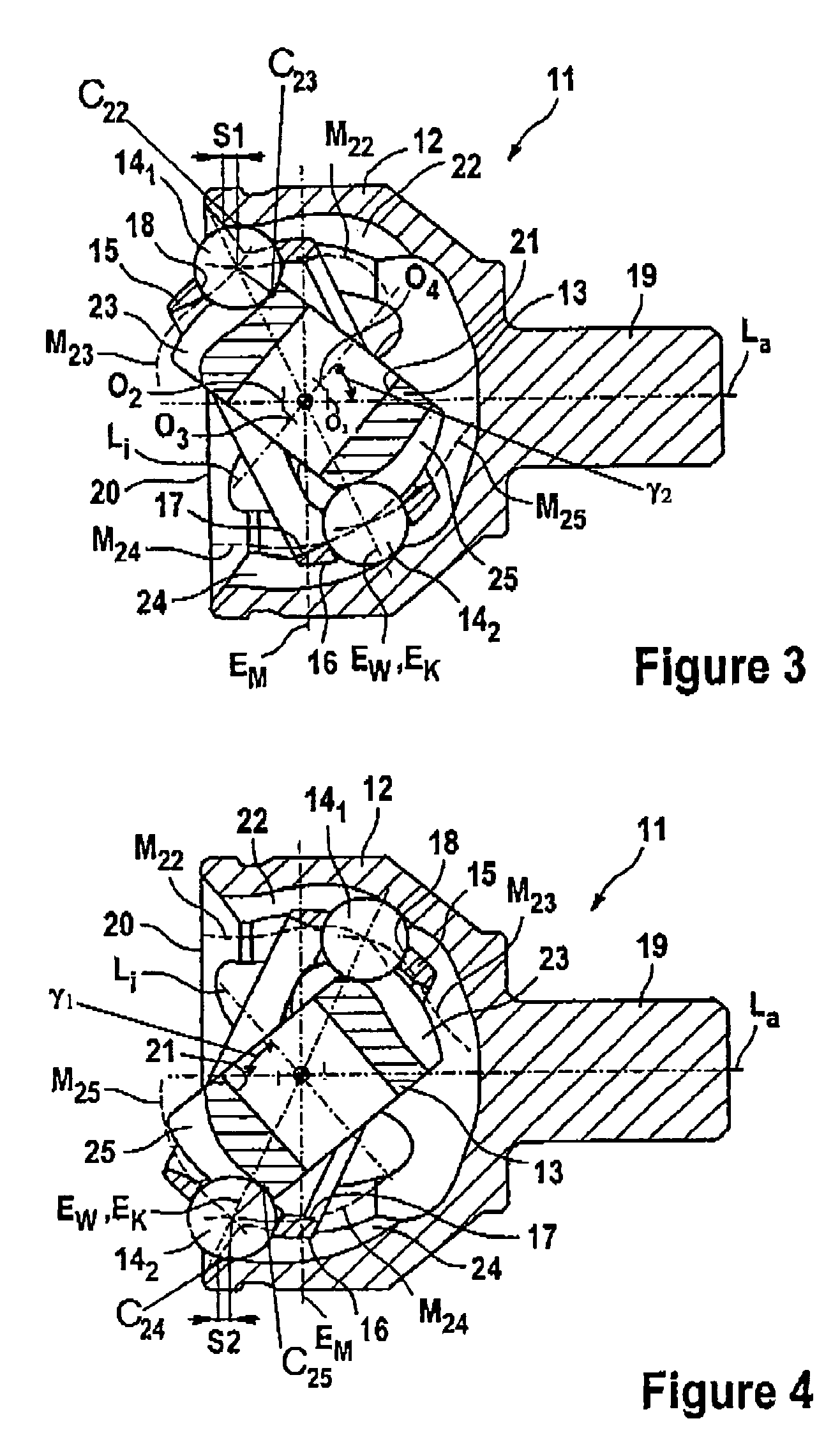
[0050]FIGS. 1 to 4 will initially be described jointly below. They each show a longitudinal section through an inventive joint 11 which, substantially, comprises an outer joint part 12, an inner joint part 13, torque transmitting balls 14 and a ball cage 15. By way of a spherical outer face 16, the ball cage 15 is held concentrically in the outer joint part 12, whereas, by way of its inner face 17, the ball cage 15 is preferably held with play relative to the inner joint part 13. The balls 14 are held in circumferentially distributed cage windows 18 in the ball cage 15 in a common central ball plane EK. The outer joint part 12 is shown to comprise a longitudinal axis La and the inner joint part 13 defines a longitudinal axis Li. The outer joint part 12 comprises an attaching journal 19 and an aperture 20. The position of the attaching journal 19 indicates the axial direction of the “attaching end” and the position of the aperture 20 indicates the axial direction of the “aperture end...


PUM


Abstract

A constant velocity counter track joint having an outer joint part (12) and an inner joint part forming first and second pairs of tracks (22, 23; 24, 25) each accommodating a torque transmitting ball (14), and a ball cage (15) with windows (18) each receiving at least one of the balls (14). When the joint is aligned, the opening angle (α) of the first pairs of tracks (22, 23) opens from the aperture end to the attaching end, and the opening angle (β) of the second pairs of tracks (24, 25) opens from the attaching end to the aperture end. The first pairs of tracks (22, 23) are designed in such a way that, when the joint is articulated, the opening angle (α) of the first pairs of tracks (22, 23), at a ball (14) entering the outer joint part (12) via the central plane (EM), initially becomes zero and then opens towards the aperture end.

Description

TECHNICAL FIELD[0001]The invention relates to a constant velocity universal ball joint in the form of a counter track joint.BACKGROUND OF THE INVENTION[0002]Counter track joints are described in DE 100 60 119 A1, for example. Counter track joints typically comprise an outer joint part which includes a first longitudinal axis (La), an attaching end and an aperture end which are positioned axially opposite one another, as well as first outer ball tracks and second outer ball tracks. The outer joint part works with an inner joint part which comprises a second longitudinal axis (Li) and an attaching mechanism for a shaft pointing towards the aperture end of the outer joint part, as well as first inner ball tracks and second inner ball tracks. The first outer ball tracks and the first inner ball tracks form first pairs of tracks with one another. The second outer ball tracks and the second inner ball tracks form second pairs of tracks with one another. The pairs of tracks each accommodat...

Claims


Application Information

Patent Timeline
IPC IPC(8): F16D3/223F16D3/2233F16D3/2237
CPCF16D3/223F16D3/2233F16D3/2237Y10S464/906F16D2003/22306F16D2003/22309
Inventor WECKERLING, THOMAS
Owner GKN AUTOMOTIVE GMBH
Why Eureka
Try Eureka