Algorithm for real-time process control of electro-polishing

a real-time process and electro-polishing technology, applied in the direction of programme control, lapping machines, instruments, etc., can solve the problems of time-consuming methods, impede the accurate determination of the polishing endpoint, and the progress of the polishing operation is not easily viewabl

Inactive Publication Date: 2006-09-26
APPLIED MATERIALS INC
View PDF131 Cites 3 Cited by
  • Summary
  • Abstract
  • Description
  • Claims
  • Application Information

AI Technical Summary

Problems solved by technology

However, the progress of the polishing operation is not easily viewable because of the contact between the wafer and the pad.
In addition, variations in the polishing conditions impede an accurate determination of the polishing endpoint.
However, this method is time consuming, and does not account for sudden changes in the removal rate that may occur between measurement intervals.
However, this method does not provide a way of determining the polishing endpoint unless an underlying layer is exposed during polishing.
Additionally, this approach is somewhat erratic in predicting the polishing endpoint unless all of the underlying lines are simultaneously exposed.
Furthermore, the detection apparatus is delicate and subject to frequent breakdown caused by the exposure of the measuring or detecting apparatus to the slurry or electrolytic fluid.
This affects the torque necessary to provide the desired polishing pad speed.
Such changes may mask the exposure of the underlying metal layer, or they may imitate an endpoint condition, leading to a premature stop of polishing.
Thus, while the endpoint detection techniques (including those described above) exist for CMP, the techniques may not be readily extendible to ECMP.
Even where the techniques are extendible to ECMP, doing so may require retrofitting existing processing systems with expensive equipment.

Method used


Image

  • Algorithm for real-time process control of electro-polishing
  • Algorithm for real-time process control of electro-polishing
  • Algorithm for real-time process control of electro-polishing

Examples


example

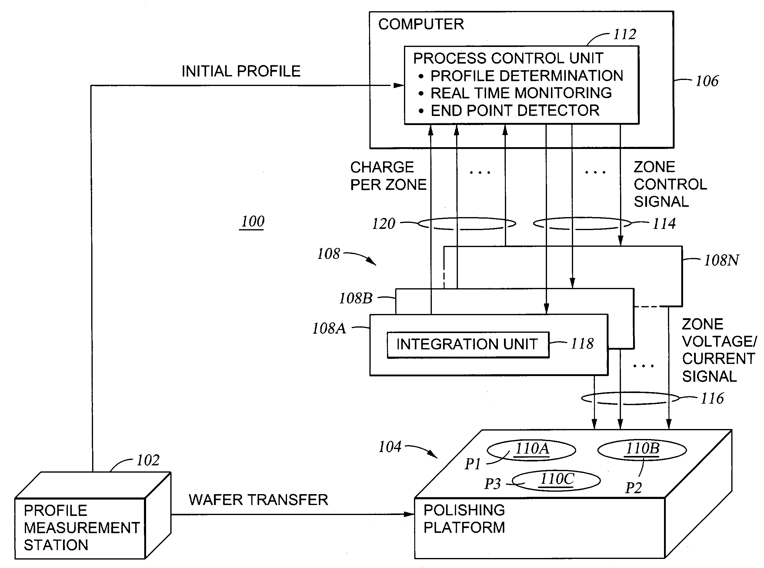
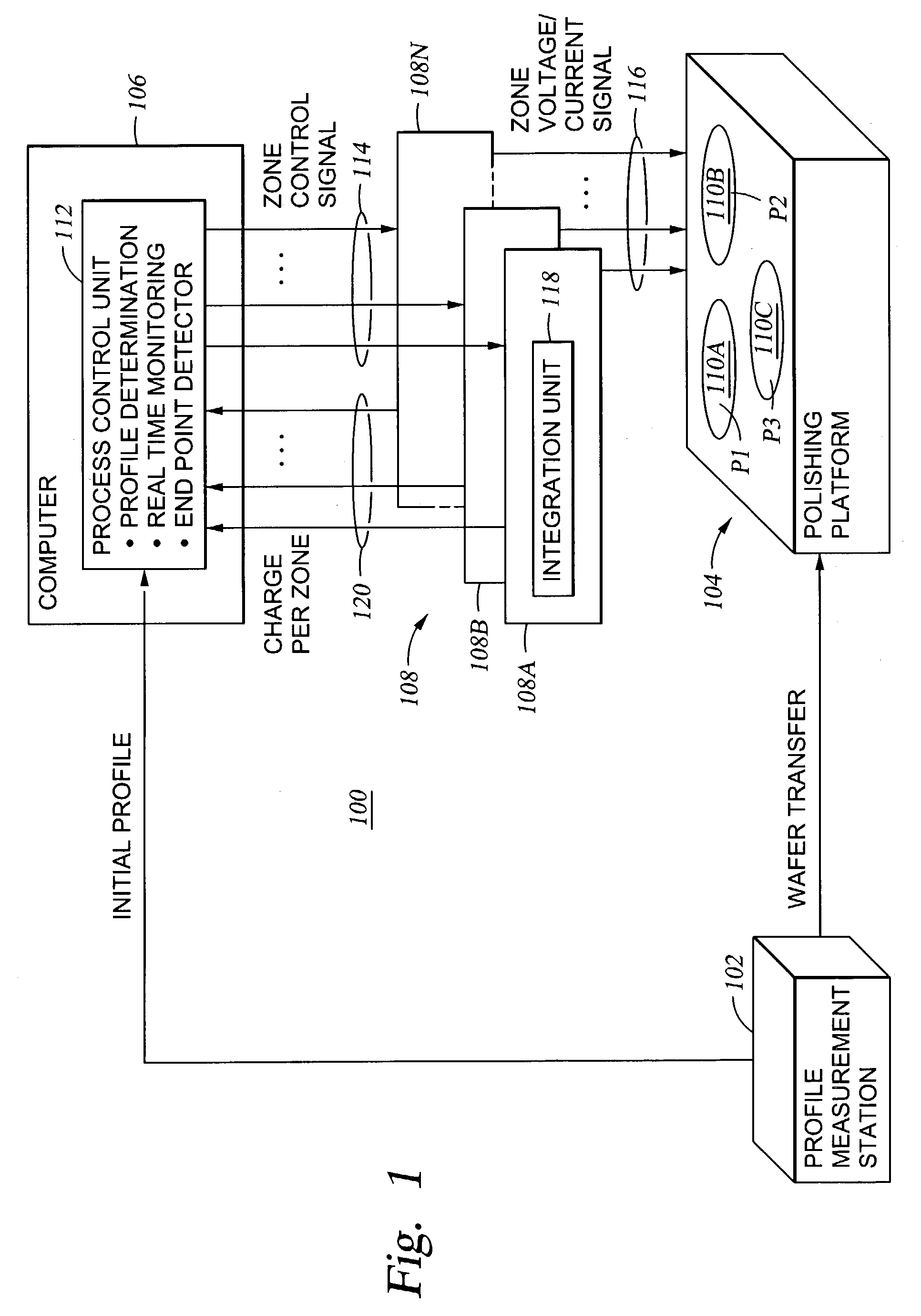
[0089]A counter-electrode assembly, such as the counter-electrode assembly 209 was divided into five zones: an inner zone, an inner-central zone, a central zone, an outer-central zone and an outer zone (Z1, Z2, Z3, Z4 and Z5) respectively. The zones were arranged in a concentric circular manner similar to the zones depicted for the electrode assembly 209 shown in FIG. 4. Each of the zones was capable of receiving a separate bias with respect to a material layer of a wafer to be polished. One hundred twenty one points, representing a broad sampling of various locations on the material layer were selected. A pre-determined set of instructions (i.e., a polishing program) that encoded a sequence of relative motion between the counter-electrode (as well as the polishing article) and the material layer of a wafer to be processed was provided to a computer (e.g., the computer 106). An algorithm based on the polishing program was used to determine the sequence of relative positions between ...


PUM


Abstract

Method and apparatus for process control of electro-processes. The method includes electro-processing a wafer by the application of two or more biases and determining an amount of charge removed as a result of each bias, separately. In one embodiment, an endpoint is determined for each bias when the amount of charge removed for a bias substantially equals a respective target charge calculated for the bias.

Description

CROSS-REFERENCE TO RELATED APPLICATIONS[0001]This application is a continuation-in-part of U.S. patent application Ser. No. 10 / 244,688, now U.S. Pat. No. 6,848,970, filed Sep. 16, 2002, entitled PROCESS CONTROL IN ELECTROCHEMICALLY ASSISTED PLANARIZATION and U.S. patent application Ser. No. 10 / 391,324, filed Mar. 18, 2003, entitled PROCESS CONTROL IN ELECTRO-CHEMICAL MECHANICAL POLISHING, herein incorporated by reference.BACKGROUND OF THE INVENTION[0002]1. Field of the Invention[0003]The present invention generally relates to polishing, planarization, plating and combinations thereof. More particularly, the invention relates to the monitoring and control of electro-processing, polishing and plating.[0004]2. Description of the Related Art[0005]Sub-quarter micron multi-level metallization is one of the key technologies for the next generation of ultra large-scale integration (ULSI). The multilevel interconnects that lie at the heart of this technology require planarization of intercon...

Claims


Application Information

Patent Timeline
Patent Type & Authority Patents(United States)
IPC IPC(8): H05K3/07B23H5/06B23H5/08B24B37/013B24B37/04B24B49/04B24B49/16C25F3/02C25F3/22C25F3/30C25F7/00G01B7/06H04N1/00
CPCB23H5/06B23H5/08B24B37/013B24B37/042B24B37/046H04N1/00B24B49/16C25F3/02C25F7/00B24B49/04G05B2219/45232G05B2219/49085
Inventor MANENS, ANTOINE P.DUBOUST, ALAINNEO, SIEW S.CHEN, LIANG-YUH
Owner APPLIED MATERIALS INC
Why Eureka
Try Eureka