Force sensing resistor with calibration element and method of manufacturing same

a technology of force sensing resistor and calibration element, which is applied in the direction of force measurement, instruments, computing, etc., can solve the problems of limiting the usefulness of the fsr to situations, and the tolerance of manufacturing between the fsrs of pressure transducers manufactured over time may be +/25%

Active Publication Date: 2006-09-26
INTERLINK ELECTRONICS
View PDF41 Cites 55 Cited by
  • Summary
  • Abstract
  • Description
  • Claims
  • Application Information

AI Technical Summary

Benefits of technology

[0010]It is another object of the present invention to provide an FSR having a calibration element which corrects the FSR for effects caused by manufacturing variations.
[0011]It is a further object of the present invention to provide an FSR having a calibration element which corrects the FSR for effects caused by temperature variations.
[0012]It is still another object of the present invention to provide an FSR having a calibration element which corrects the FSR for effects caused by humidity variations.
[0013]It is still a further object of the present invention to provide a method of manufacturing an FSR having a calibration element which corrects the FSR for effects caused by manufacturing and environmental variations.

Problems solved by technology

When an FSR is used in changing humidity conditions, the high humidity resistance coefficient of the FSR ink limits the usefulness of the FSR to situations where only changes in force may be measured.
A problem is that manufacturing tolerances between the FSRs of pressure transducers manufactured over time may be + / −25%.
These tolerance variances are caused by day-to-day and batch-to-batch FSR ink inconsistencies and by daily variations in manufacturing equipment setup.

Method used


Image

  • Force sensing resistor with calibration element and method of manufacturing same
  • Force sensing resistor with calibration element and method of manufacturing same
  • Force sensing resistor with calibration element and method of manufacturing same

Examples


Embodiment Construction

)

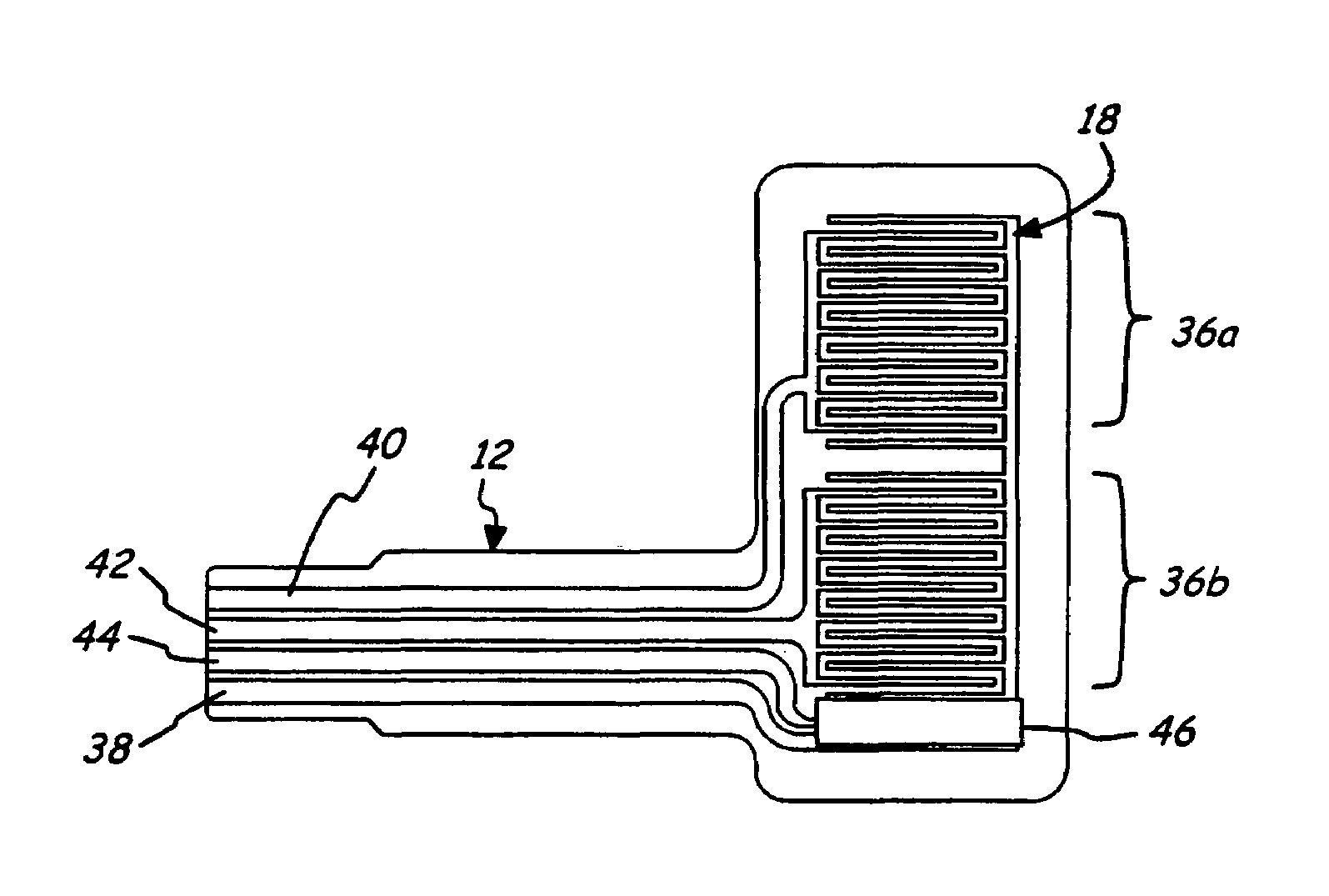
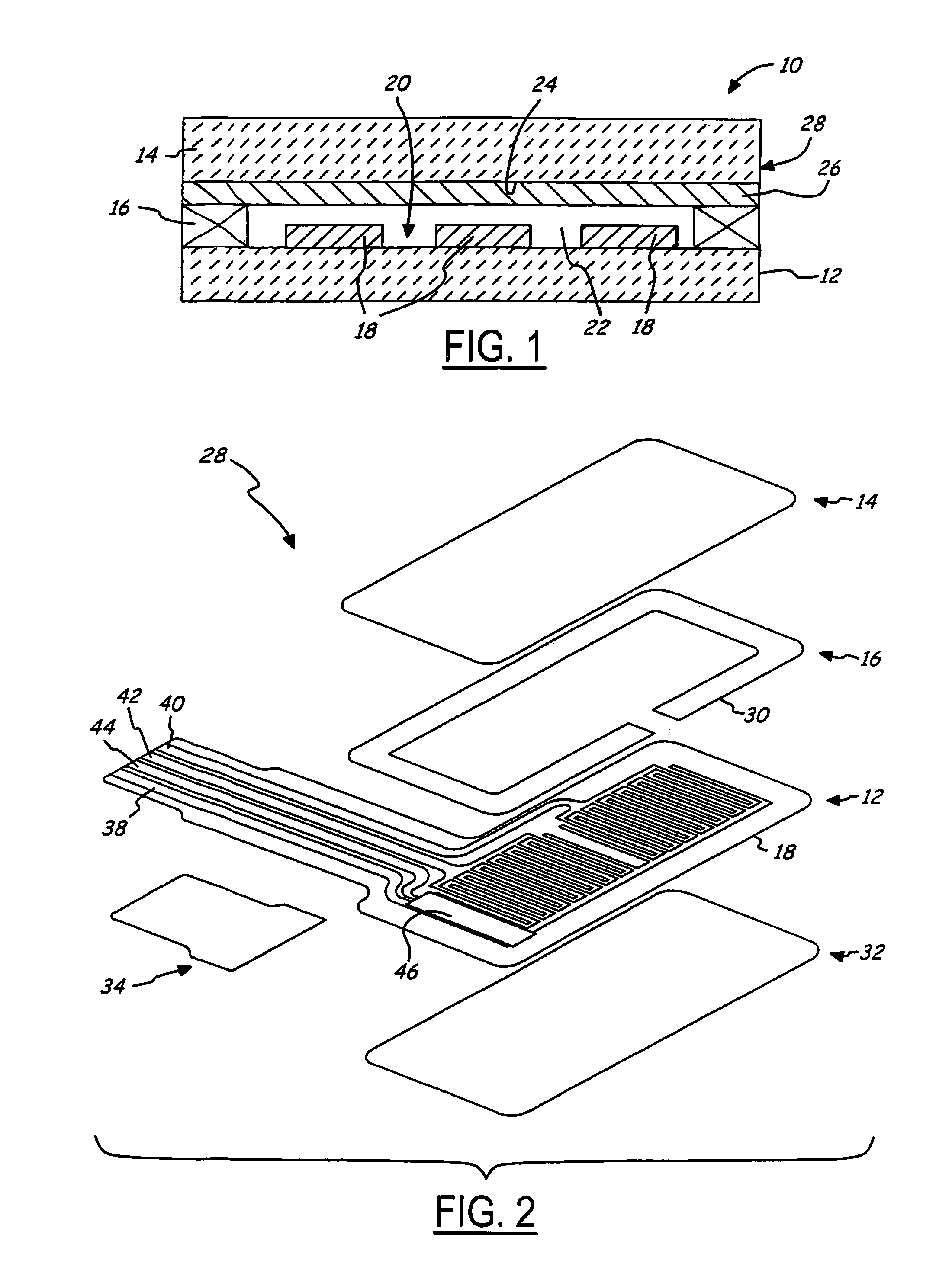
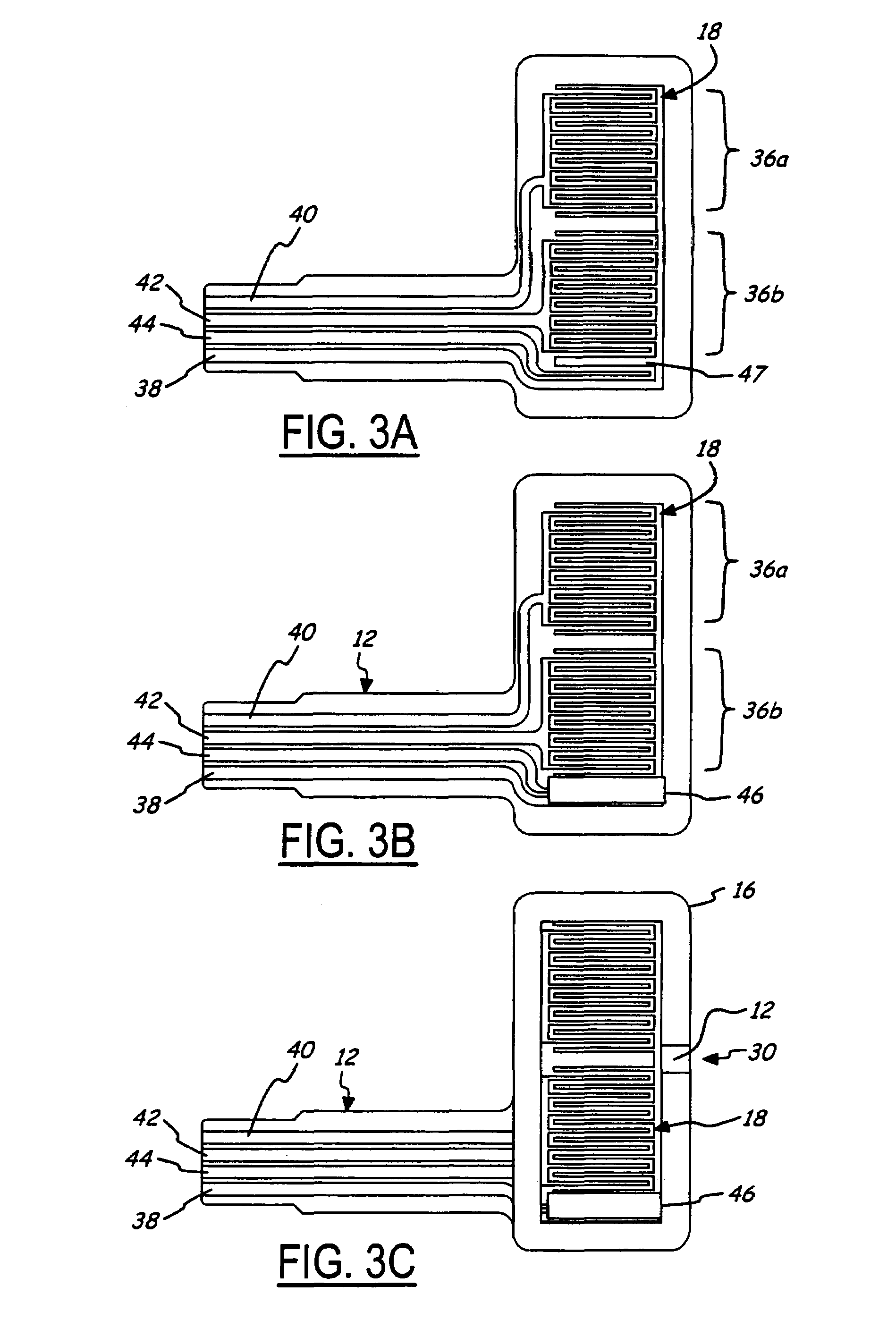
[0039]Referring now to FIG. 1, a cross-sectional view of a pressure sensitive transducer 10 having a force sensing resistor (FSR) in accordance with the present invention is shown. Pressure transducer 10 produces an electrical signal indicative of applied pressure. Pressure transducer 10 generally includes a first flexible substrate 12, a second flexible substrate 14, and a spacer 16. Flexible substrates 12 and 14 are individual portions obtained from the same flexible sheet of material such as, for example, Mylar. In response to one of substrates 12 and 14 being touched by an actuator or finger, this substrate deforms and moves toward the other one of the substrates. For example, second substrate 14 deforms and moves inward toward first substrate 12 in response to being touched.

[0040]Electrically conductive traces 18 are formed on first substrate 12 to define contact area 20. Spacer 16 attaches first and second substrates 12 and 14 together in such a manner that the substrates are...


PUM


Abstract

A force sensing resistor includes two substrates. Conductive traces including first, common, and calibration fingers are on the first substrate and define a contact area. A spacer surrounds the contact area and attaches the substrates together such that a cavity separates the substrates in the contact area. A first resistive layer is on the second substrate and arranged within the cavity. In response to a force moving one substrate, the first resistive layer electrically connects the first and common fingers with a resistance dependent upon resistivity of the first resistive layer and the applied force to produce an electrical signal indicative of the applied force. A second resistive layer is arranged within the cavity and electrically connects the calibration and common fingers with a resistance dependent upon resistivity of the second resistive layer to produce an electrical signal indicative of the resistivity of the second resistive layer.

Description

BACKGROUND OF THE INVENTION[0001]1. Field of the Invention[0002]The present invention generally relates to force sensing resistors and, more particularly, to a force sensing resistor (FSR) having a calibration element and to a method of manufacturing such an FSR.[0003]2. Background Art[0004]Pressure sensitive transducers (“pressure transducers”) generate a signal indicative of the amount of pressure applied to a flexible substrate. Pressure transducers may also generate a signal based on the location of pressure applied to the flexible substrate. Pressure transducers provide input for a wide variety of applications such as remote controls, game controllers, mouse pads, tactile sensors, and the like.[0005]A construction for a pressure transducer includes one or more force sensing resistors (FSR). Various FSRs have been disclosed, such as those described in U.S. Pat. Nos. 4,314,227; 4,314,228; and 4,489,302. A typical FSR includes three parts: a (flexible or rigid) base, a spacer, and...

Claims


Application Information

Patent Timeline
Patent Type & Authority Patents(United States)
IPC IPC(8): G09G5/00G06F3/045
CPCG01L1/205
Inventor BAKER, JEFFREY R.SANCHEZ, CARLOS S.
Owner INTERLINK ELECTRONICS
Why Eureka
Try Eureka