Manufacturing method of liquid discharge head

a manufacturing method and liquid discharge technology, applied in the direction of printing, coating, pretreatment surfaces, etc., can solve the problem that the manufacturing method is similar, and achieve the effect of hardly causing a variation in liquid discharge properties, excellent formation, and good shape precision

Inactive Publication Date: 2011-08-25
CANON KK
View PDF22 Cites 2 Cited by
  • Summary
  • Abstract
  • Description
  • Claims
  • Application Information

AI Technical Summary

Benefits of technology

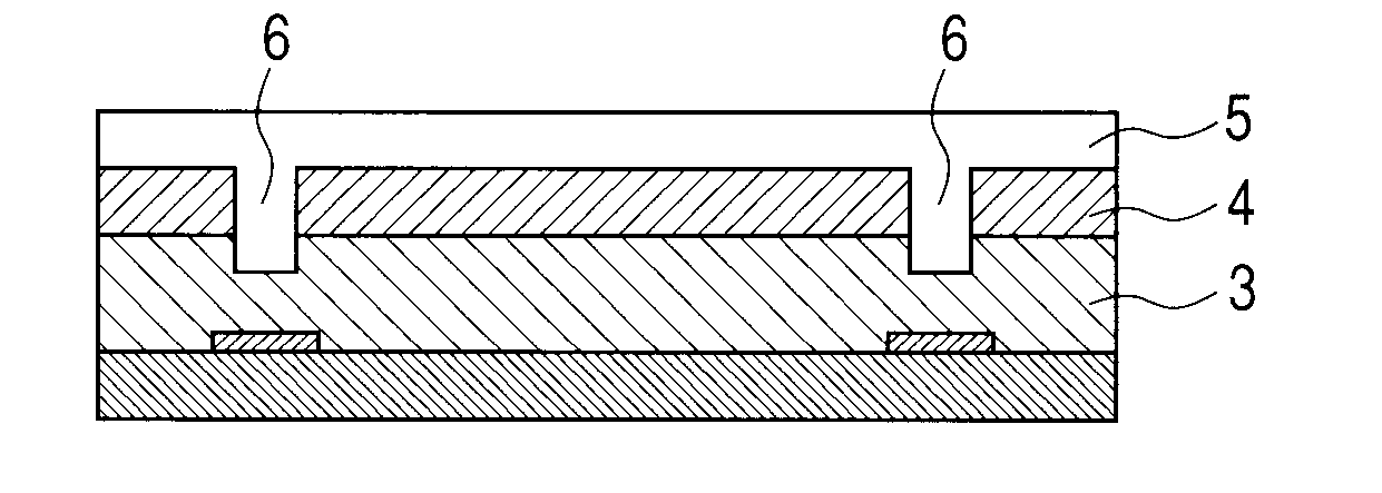
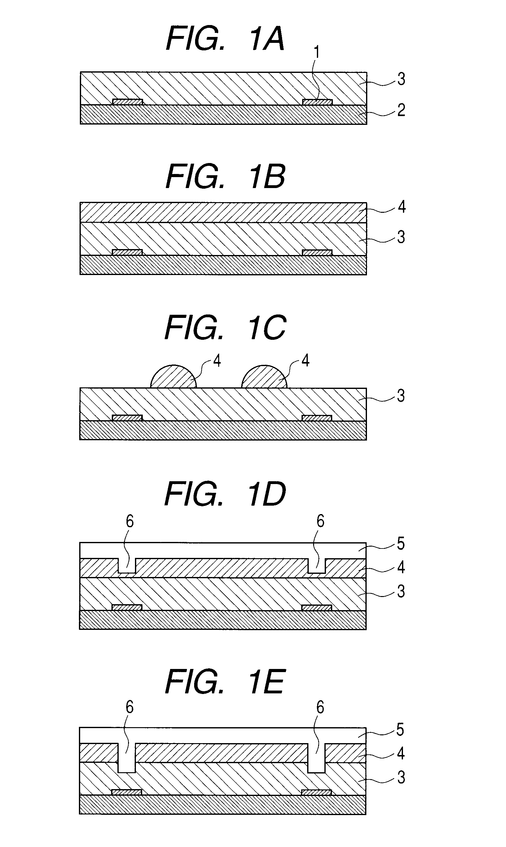
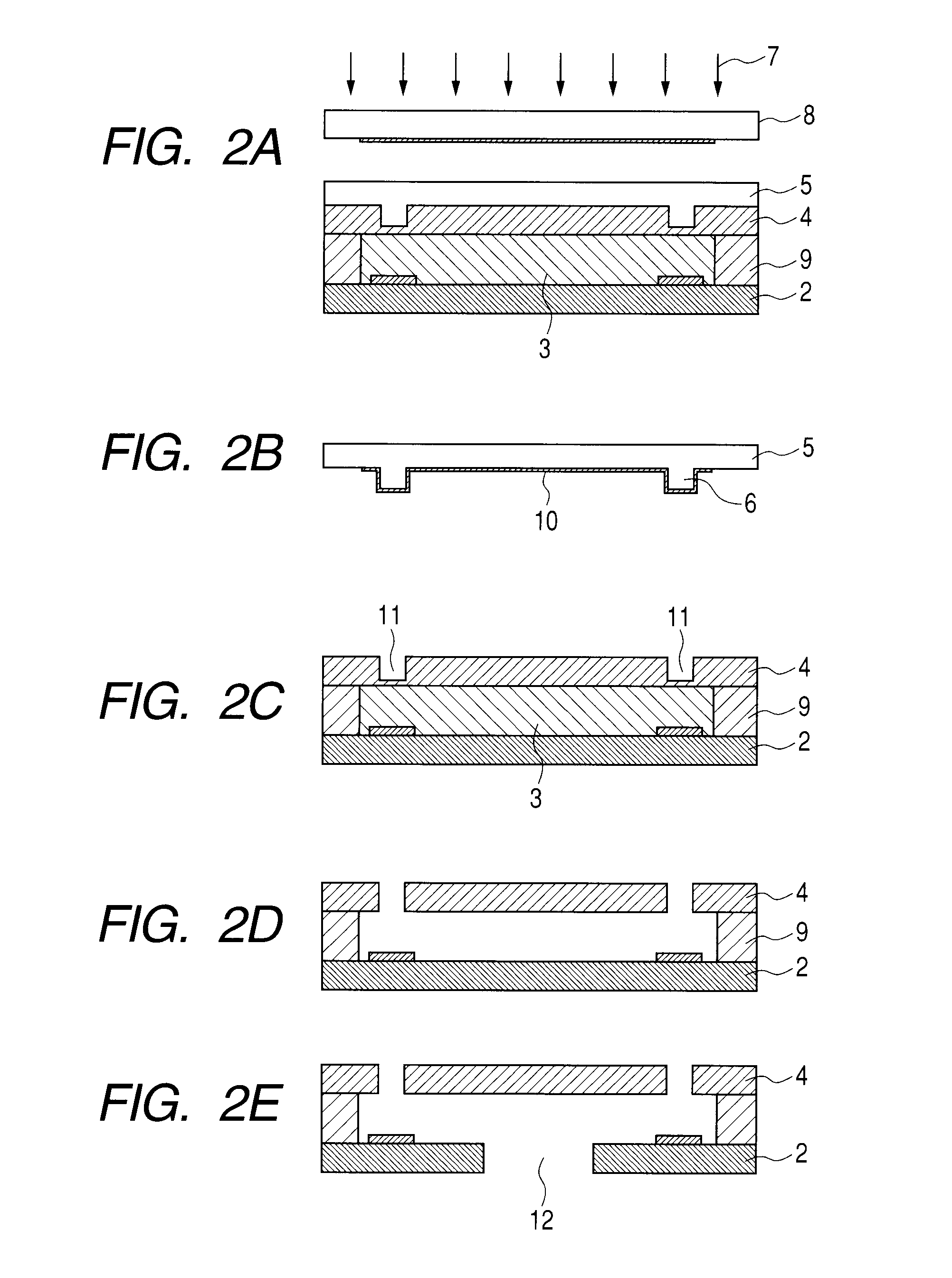
[0008]In light of the above, an object of the present invention is to provide a manufacturing method of a liquid discharge head, which can manufacture a liquid discharge head having a liquid flow path excellently formed with good shape precision and discharge ports and hardly causing a variation in liquid discharge properties, with a smaller number of manufacturing steps.
[0016]According to the present invention, it is possible to provide a manufacturing method of a liquid discharge head, which can manufacture a liquid discharge head having a liquid flow path excellently formed with good shape precision and discharge ports and hardly causing a variation in liquid discharge properties, with a smaller number of manufacturing steps.

Problems solved by technology

Both of the methods, however, require a step of bonding the manufactured orifice plate to the substrate having the ink flow path wall and ink discharge energy generating elements manufactured by some method.
Accordingly, this manufacturing method has a problem similar to those of the manufacturing methods of an inkjet recording head described in Japanese Patent Application Laid-Open No. 2006-198779 and Japanese Patent Application Laid-Open No. 2007-176076.

Method used


Image

  • Manufacturing method of liquid discharge head
  • Manufacturing method of liquid discharge head
  • Manufacturing method of liquid discharge head

Examples


embodiment

Embodiment 1

Manufacturing of Master Mold 1

[0060]Firstly, a positive type resist, OFPR-800 (trade name) produced by Tokyo Ohka Kogyo Co., Ltd., was applied onto a quartz substrate. The quartz substrate was exposed to light using a mask of an ink discharge port pattern, and then developed. Subsequently, the surface of the substrate was etched by reactive ion etching (RIE) using the pattern of OFPR-800 as a mask to produce protrusions of the ink discharge port pattern, and then the OFPR-800 was separated from the substrate. At that time, the height of the protrusions of the ink discharge port pattern was about 10 μm.

[0061]Subsequently, an aluminum (Al) film was formed, by thermochemical vapor deposition (CVD), on the surface of the quartz substrate where the protrusions were formed. The quartz substrate was heated to 300° C., and trimethylaluminum (TMA) was used as a source gas. The Al film was formed on not only end surfaces and bottom surface of the quartz substrate but also on side ...

embodiment 2

Manufacturing of Inkjet Recording Head 1

[0064]Firstly, an ink supply port was formed in a rear surface of a silicon substrate on which surface electro-thermal converting elements were formed as ink discharge energy generating elements. Specifically, a cyclized rubber resist was applied, as a protective film, onto the surface of the silicon substrate where the electro-thermal converting elements were formed. Subsequently, a silicon oxide which had been preliminarily formed on the rear surface of the silicon substrate was patterned, and using the patterned silicon oxide as a mask, the silicon substrate was immersed in a tetramethylammonium hydroxide aqueous solution (22%, 83° C.) for 16 hours. Then, the silicon substrate was subjected to anisotropic etching to form an ink supply port, and then the protective film was separated from the silicon substrate.

[0065]Next, SU-8 3025 (trade name) produced by MicroChem serving as a cationically photocurable resin was formed on a PET film by sli...

embodiment 3

Manufacturing of Master Mold 2

[0072]Firstly, a positive type resist, OFPR-800 (trade name) produced by Tokyo Ohka Kogyo Co., Ltd., was applied onto a quartz substrate. The quartz substrate was exposed to light using a mask of an ink discharge port pattern, and then developed. Subsequently, the surface of the substrate was etched by reactive ion etching (RIE) using the pattern of OFPR-800 as a mask to produce protrusions of the ink discharge port pattern, and then the OFPR-800 was separated from the substrate. At that time, the height of protrusions of the ink discharge port pattern was about 10 μm.


PUM

PropertyMeasurementUnit
heightaaaaaaaaaa
thicknessaaaaaaaaaa
thicknessaaaaaaaaaa

Abstract

This invention relates to a manufacturing method of a liquid discharge head comprising: forming an active energy ray-curable resin layer on a surface of a substrate on which discharge energy generating elements are formed, attaching a material permeable to active energy rays onto a surface of the active energy ray-curable resin layer, pressing against the material permeable to active energy rays, a master mold being transparent to the active energy rays and having protrusions corresponding to a pattern of discharge ports so as to transfer the protrusions to the material permeable to active energy rays, selectively irradiating the active energy ray-curable resin layer with active energy rays according to a pattern of liquid flow paths so as to cure the active energy ray-curable resin layer, removing the master mold, and removing uncured portions of the active energy ray-curable resin layer.

Description

TECHNICAL FIELD[0001]The present invention relates to a forming method of a structure and a manufacturing method of an inkjet head.BACKGROUND ART[0002]There have been disclosed manufacturing methods of an inkjet recording head using nano-imprinting lithography and similar techniques, which are described in Japanese Patent Application Laid-Open No. 2006-198779, Japanese Patent Application Laid-Open No. 2007-176076, and U.S. Pat. No. 5,818,479.[0003]Japanese Patent Application Laid-Open No. 2006-198779 discusses a manufacturing method of an inkjet recording head, in which firstly, a resin film and a mold member (master mold) having protrusions are heated, and the resin film is pressed against the mold member to form through-holes in the resin film. Subsequently, the resin film is laminated, as an orifice plate, onto a substrate where ink discharge energy generating elements and an ink flow path are formed, thereby manufacturing an inkjet recording head.[0004]Japanese Patent Applicatio...

Claims


Application Information

Patent Timeline
Patent Type & Authority Applications(United States)
IPC IPC(8): B29C71/04
CPCB41J2/1603B41J2/1637B41J2/1631
Inventor SAITO, YOSHIKAZUISHIKURA, HIROESUZUKI, TAKUMISATO, TAMAKIYONEYAMA, HIRONOMORISUE, MASAFUMIKANRI, RYOJI
Owner CANON KK
Why Eureka
Try Eureka