Decomposition architecture for an MCU

a technology of decomposition architecture and mcu, applied in the field of multimedia communication, can solve the problems of mc not performing mixing or switching of audio, video and data, signaling, control and media multiplexing, and the limited capacity of each mcu to multimedia conferences

Inactive Publication Date: 2006-09-26
POLYCOM INC
View PDF31 Cites 50 Cited by
  • Summary
  • Abstract
  • Description
  • Claims
  • Application Information

AI Technical Summary

Benefits of technology

[0020]The attributes of contexts are ContextID and the topology (who hears / sees whom). An exemplary context can be a videoconference of 3 participants: one is using an H.323 endpoint and two are using H.320 endpoint with bit rate that is different from the first one. This context includes the following terminations: three networks I / F ports, one RTP, two MUXes, an audio mixer and a video mixer. The present invention implements a DMCU by using the connection model and protocol that is described in H.248. The present invention allows communication and resources sharing between plurality of MCs and MPs.

Problems solved by technology

Additionally, the capacity of each MCU is limited to multimedia conferences controlled by the corresponding MCU.
However, the MC does not perform mixing or switching of audio, video and data.
One difficulty in operating the DMCU with other standards, such as H.320, is that signaling, control and media are multiplexed.

Method used


Image

  • Decomposition architecture for an MCU
  • Decomposition architecture for an MCU
  • Decomposition architecture for an MCU

Examples


Embodiment Construction

[0028]Referring now to the drawings, in which like numerals refer to like parts throughout the several views, exemplary embodiments of the present invention are described.

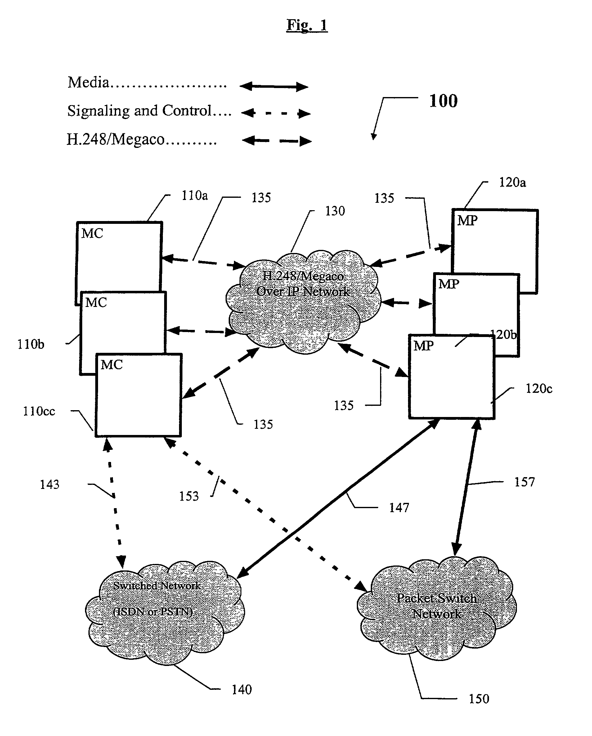
[0029]FIG. 1 is a system diagram that illustrates an exemplary operator site 100 implementing various embodiments of the present invention. The site 100 may include one or more DMCUs: (110a; 120a); (110b; 120b) and (110c; 120c). An exemplary DMCU comprises of one MC (110a; 110b; 110c) and one MP (120a; 120b; 120c) respectively. Although three DMCUs are illustrated, the present invention is not limited to a particular number of DMCUs and the presented configuration is intended to be illustrative of an exemplary configuration. An MC can control one or more MPs. The connection between the MC and MP that compose a DMCU is based on H.248 / Megaco over IP it may be over an Intranet 130, Internet LAN, or direct connection. The MCs and the MPs may be co-located or geographically dispersed.

[0030]In an exemplary system, each D...


PUM


Abstract

The present invention allows the resources of multiple multipoint control units (MCUS) in a multipoint multimedia communication system. A plurality of multimedia terminals support different multimedia conferencing protocols, and a multipoint control unit communicates with a multipoint processor unit and with the multimedia terminals for signaling and call control. At least one multipoint processor unit communicates with the plurality of multimedia terminals for media and optionally call signaling and call control. The multipoint processor unit also communicates with the multipoint control unit for interfacing the call signaling and the call control information between said multipoint control unit and the terminals.

Description

RELATED APPLICATIONS[0001]This application is a continuation-in-part of U.S. patent application Ser. No. 09 / 708,898, filed Nov. 8, 2000, the contents of which are incorporated herein by reference. The present application further claims the benefit of priority from U.S. Provisional Application Ser. No. 60 / 164,298 filed Nov. 8, 1999, the contents of which are incorporated herein by reference.FIELD OF THE INVENTION[0002]This invention relates generally to multimedia communications, and more specifically, to a system and method for decomposing a multipoint multimedia communication system to control unit and process unit.BACKGROUND[0003]As the geographical domain in which companies conduct business continues to expand, the traffic of multimedia teleconferencing overloads multimedia communication central nodes. In the current market, most multipoint multimedia calls are scheduled in advance through companies that own multipoint control units (MCUs). An MCU provides the capability for thre...

Claims


Application Information

Patent Timeline
Patent Type & Authority Patents(United States)
IPC IPC(8): G06F15/16H04N7/14H04N7/15
CPCH04N7/148H04L12/1822H04N7/15H04L12/18
Inventor EVEN, RONI
Owner POLYCOM INC
Why Eureka
Try Eureka