
Internally illuminated knitting or crochet needle

a technology illumination, which is applied in the field of internal illumination of knitting or crochet needles, can solve the problems of lack of good working light, limited level of illumination, and centuries-old age, and achieve the effects of reducing eye strain, improving comfort in viewing the work field, and high intensity

Inactive Publication Date: 2006-10-03
WIDGET PROD
View PDF7 Cites 13 Cited by
  • Summary
  • Abstract
  • Description
  • Claims
  • Application Information

AI Technical Summary

Benefits of technology

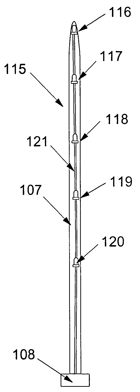
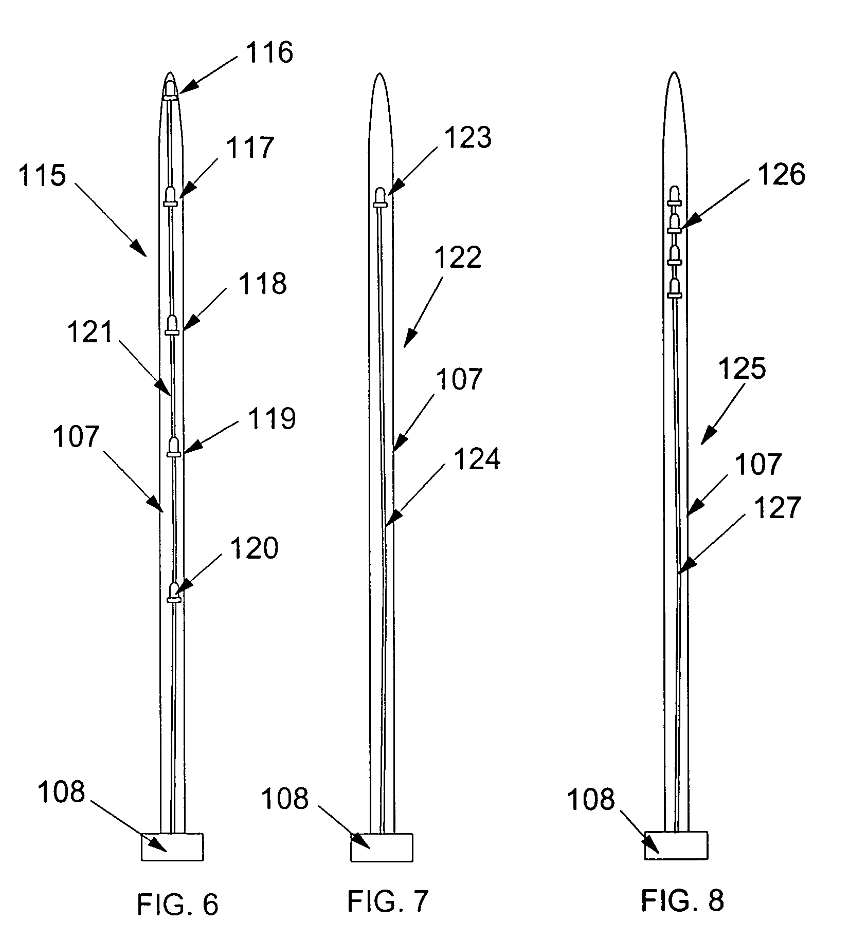
[0011]The present invention allows a user to choose from one of many shaft locations, colors and light intensities for LED's embedded or located in the shaft of a knitting or crocheting needle. The many hours a user spends in the knitting or crocheting tasks cause a user to seek out places and devices reducing eye strain and improving comfort in viewing the work field. For example, a user may prefer a white, high intensity LED to be located in a knitting needle used to receive stitches so that the user's palm will shield the user's eyes from direct view but permit the reflected light to illuminate the background of the work field and allow the user to manipulate that same needle to temporarily brightly illuminate any surface around the user when the user's palm is removed from its covering position. A user may choose to have only a low intensity blue LED at the tip of the needle used to form the stitches so that the user can easily follow the path of the needle tip into an newly formed loop on the needle bearing the stitches.
[0012]It is an object of the present invention to essentially illuminate the work field for knitting or crocheting from the inside out so the user can move their hands, fingers, needles and yarn without blocking field illumination.

Problems solved by technology

These practices, although centuries old, have consistently been accompanied by the same complaint, a lack of good working light.
The level of illumination is extremely limited and a user is required to keep the end of the device plugged in to an electrical outlet.
Unfortunately, this device is without beneficial effect as soon as a user grasps the exposed shaft and blocks the light.

Method used


Image

  • Internally illuminated knitting or crochet needle
  • Internally illuminated knitting or crochet needle
  • Internally illuminated knitting or crochet needle

Examples


Embodiment Construction

[0025]The invention is now discussed with reference to the figures.

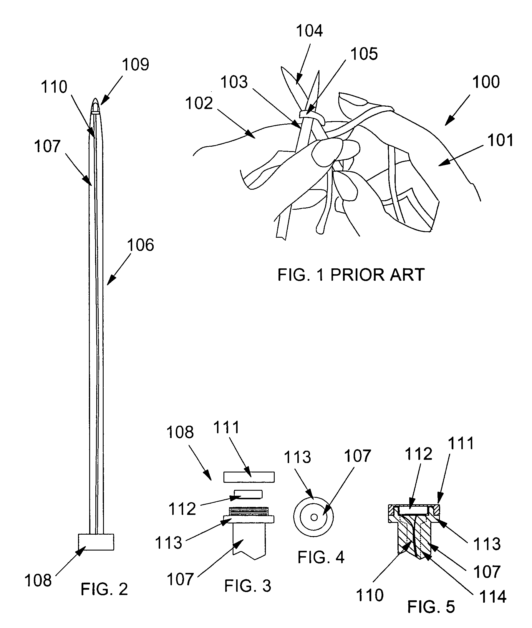
[0026]FIG. 1 shows a view of a person's hands 100 engaged in knitting, with right hand 101 grasping right needle 104 and left hand grasping left needle 103. Loop 105 has been formed by way of insertion of the tip of right needle 104 into yarn engaged on left needle 103. It may be easily appreciated that light must be directed from several sources to adequately light the work field for a user.

[0027]FIG. 2 shows an embodiment of the invention knitting needle 106 having a knob 108 rigidly connected to a proximal end of shaft 107, which extends to a pointed tip. Within the section of said tip, an LED 109 is located or embedded near to said tip and oriented so that its light emissions are effectively dispersed by the clear or translucent polymer material of shaft 107. Wires 110 connect the electrical connections of LED 109 with electrical connections for battery power and switch means for activating the battery to power L...


PUM


Abstract

The present invention is a plastic knitting or crocheting needle incorporating in the shaft one or more light emitting diodes powered by a battery source in a knob end of the needle. In a preferred embodiment, one or more LED's and their wiring are molded in a clear or translucent plastic shaft forming at least a front portion of the length of the needle, optionally having an LED embedded only in the tip or at a distance back from the tip equaling the typical needle crossing distance during knitting.

Description

BACKGROUND OF THE INVENTION[0001]The present invention relates to illumination of the site of the operation of knitting or crocheting.[0002]Knitting and crocheting are old tasks that have largely been taken over by mechanized production. However, many individuals take care and pride in personally knitting and crocheting pieces by hand. These practices, although centuries old, have consistently been accompanied by the same complaint, a lack of good working light. A person working the long hours required to make substantial progress on a knitting or crocheting project typically requires somewhat better lighting than that required for viewing flat surfaces such as in reading text. A knitter's hands are constantly moving and twisting to pull yarn, move knitting needles, check finished rows for dropped stitches or improper tension, and many other small but critical jobs. As such, a person knitting or crocheting requires light from several directions to adequately illuminate the work fiel...

Claims


Application Information

Patent Timeline
IPC IPC(8): D04B3/02
CPCD04B3/02
Inventor DREMANN, MONICA
Owner WIDGET PROD
Learn More