Select system for an automatic transmission

Inactive Publication Date: 2006-10-03
SUBARU CORP
View PDF8 Cites 18 Cited by
  • Summary
  • Abstract
  • Description
  • Claims
  • Application Information

AI Technical Summary

Benefits of technology

This patent describes a new design for a selection system used in automatic transmissions that helps avoid unintended releases of connections between levers and other components due to things like bumps while driving. This results in safer shifting experiences no matter what kind of terrain they're facing.

Problems solved by technology

The technical problem addressed in this patent is the potential for the select lever to disengage from the linkage member, resulting in an unexpected shift change from the automatic transmission mode to the manual mode. Additionally, the linkage member could accidentally be rotated due to external factors, leading to an unexpected gear change.

Method used


Image

  • Select system for an automatic transmission
  • Select system for an automatic transmission
  • Select system for an automatic transmission

Examples


Embodiment Construction

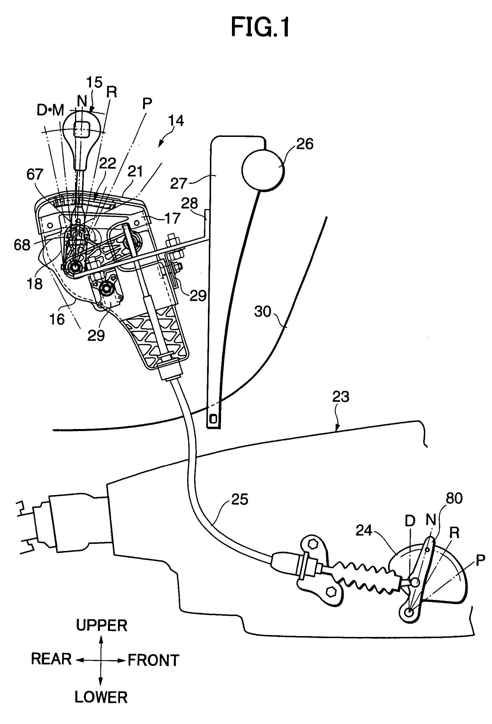
[0022]Preferred embodiments of the present invention will be hereinafter described with reference to FIG. 1 to FIG. 6.

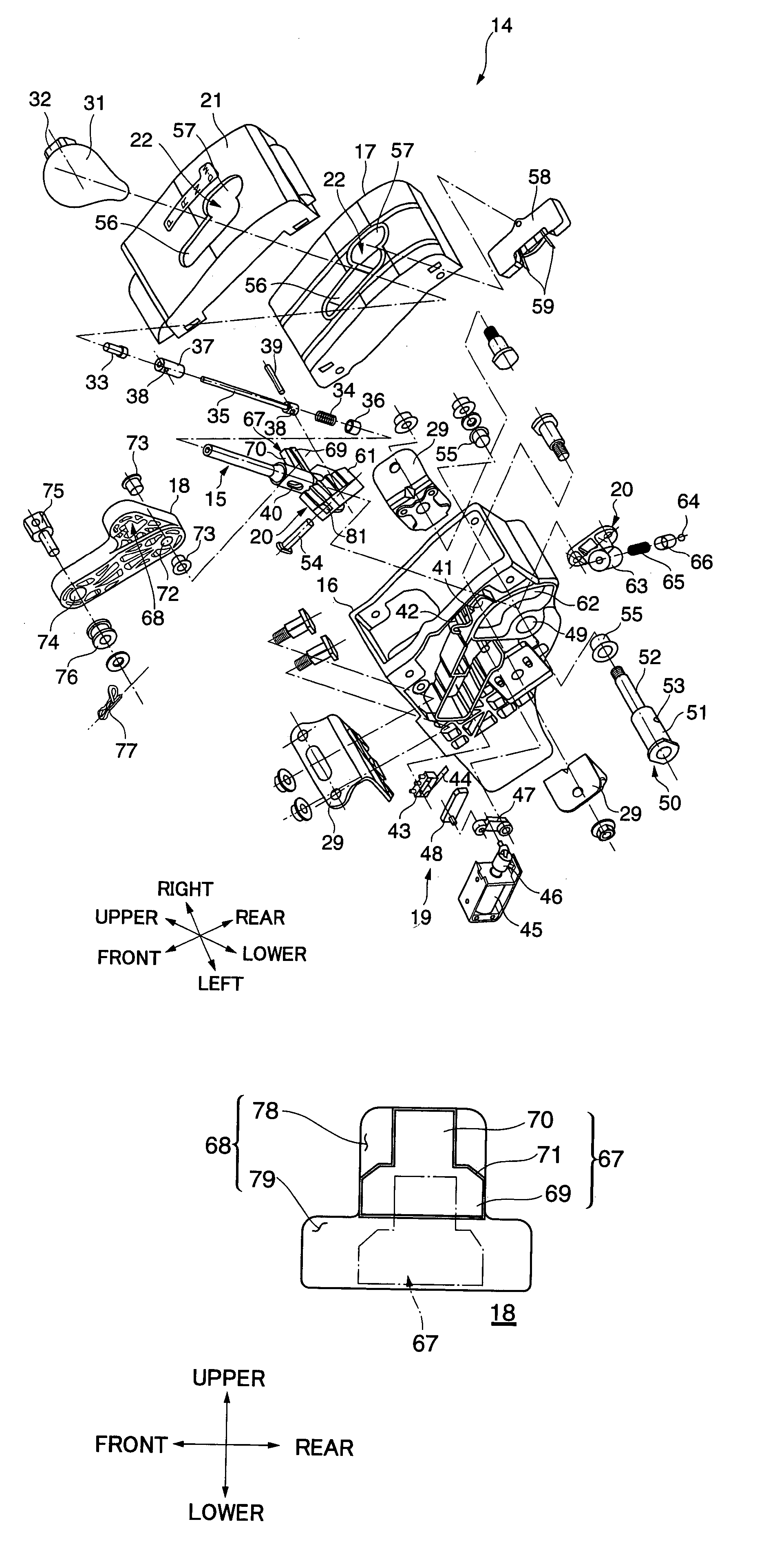
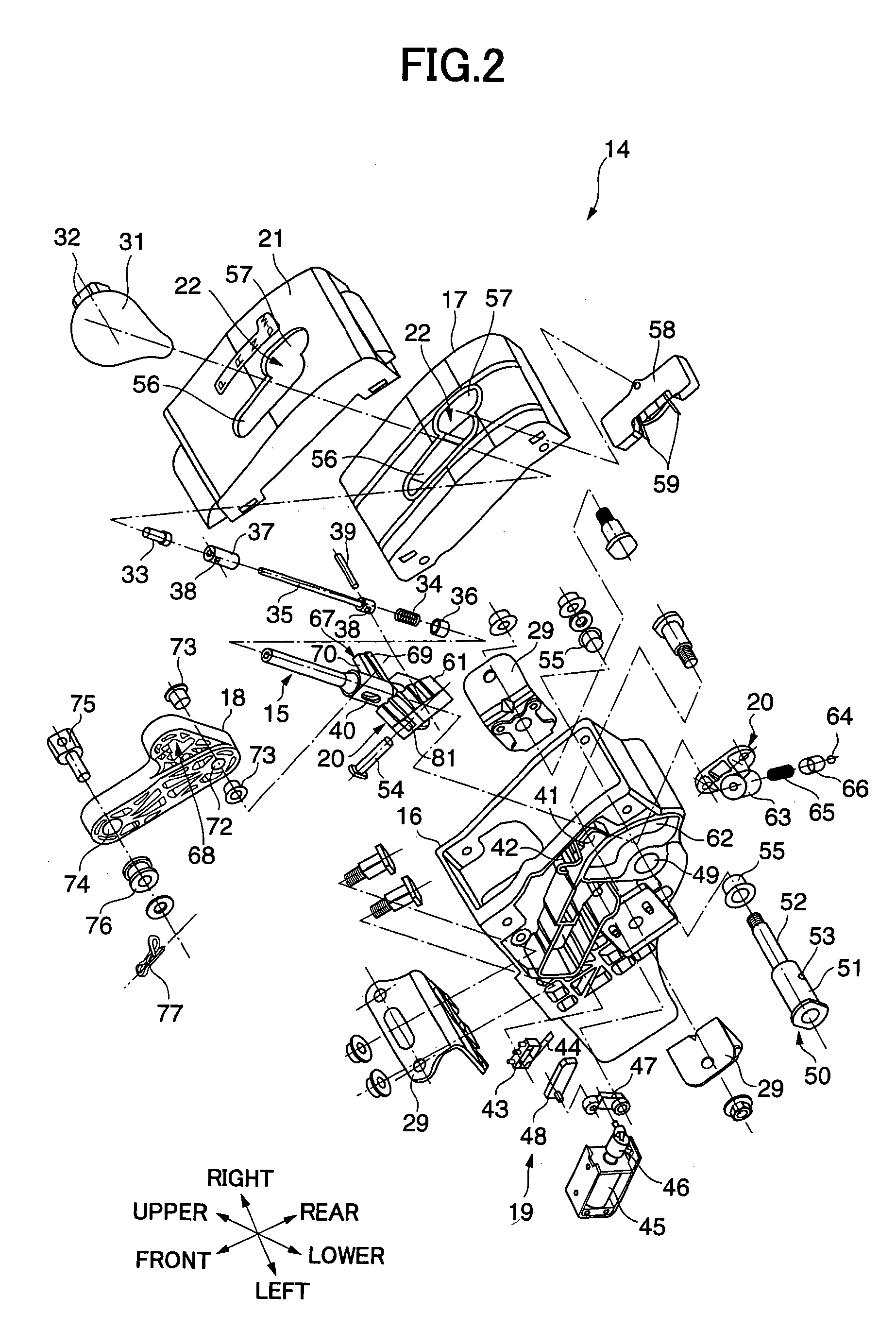
[0023]As shown in FIG. 1 through FIG. 6, a select system 14 for an automatic transmission according to the present invention has a select lever 15, a lower case 16, an upper case 17, and a linkage member 18. Shifting the select lever 15 in left and right directions (orthogonal to the plane of FIG. 1) switches between an A / T mode for mechanical positioning and a manual mode for electrical positioning. The lower case 16 to which the select lever 15 is mounted has a box-like shape having an open top and accommodates therein the linkage member 18, a shift lock mechanism 19 for retaining the lever in a selected position, a clicking gear shift mechanism 20, and a mechanism for preventing an erroneous operation, which will all be described in more detail later. The upper case 17 closes the open top of the lower case 16. Both the upper case 17 and an indicator 21 are formed ...


PUM


Abstract

In a select system for an automatic transmission in which switchover between a mechanical automatic mode and an electrical manual mode is achieved by a lateral shift of a select lever, the select lever has an engaging protrusion extending a distance to one side, which remains inserted in an engaging groove opened in a rotatable linkage member. When the select lever is in the automatic mode, the linkage member is rotatable with the lever operation by engagement between the engaging protrusion and a part of the engaging groove so as to achieve mechanical transmission control of the automatic transmission. When the select lever is in the manual mode, the engaging protrusion, while disengaging from the part of the engaging groove, restricts rotation of the linkage member so as to prevent the mechanical transmission control. Thus, the select system can prevent an accidental release of the select lever from a gear position or an unexpected shift change of the automatic transmission, whether it is in the A/T mode or manual mode.

Description


Claims


Application Information

Patent Timeline
Owner SUBARU CORP
Why Eureka
Try Eureka