Supercharge Your Innovation With Domain-Expert AI Agents!

Vacuum interrupter with a switch contact piece

a technology of switching contact and vacuum interrupter, which is applied in the direction of contacts, high-tension/heavy-dress switches, air-break switches, etc., can solve the problem that the thermal energy transmission to the surrounding environment is only possible to a limited degree, and achieve the effect of reducing the number of necessary modules, and favorable effect on the emission of hea

Inactive Publication Date: 2006-10-03
SIEMENS AG
View PDF10 Cites 12 Cited by
  • Summary
  • Abstract
  • Description
  • Claims
  • Application Information

AI Technical Summary

Benefits of technology

"The invention is about improving the cooling of a vacuum interrupter by using a strut with a first section having a larger circumference than the rest of the strut. This allows for more effective heat dissipation. The first section has openings that increase the surface area for dissipating current heat. The invention also includes a hollow body that retains the vacuum interrupter and emits thermal energy to its surrounding environment. An elastic contact element can be connected to the first sliding contact face to improve electrical and thermal contact. Overall, the invention improves the cooling and transmission of thermal energy in the vacuum interrupter."

Problems solved by technology

In particular in the case of the arrangement known from the laid-open specification DE 196 03 157 A1, transmission of thermal energy to the surrounding environment is only possible to a limited degree owing to the direct arrangement of the self-sprung contact elements on the vacuum interrupter.

Method used


Image

  • Vacuum interrupter with a switch contact piece
  • Vacuum interrupter with a switch contact piece

Examples


Embodiment Construction

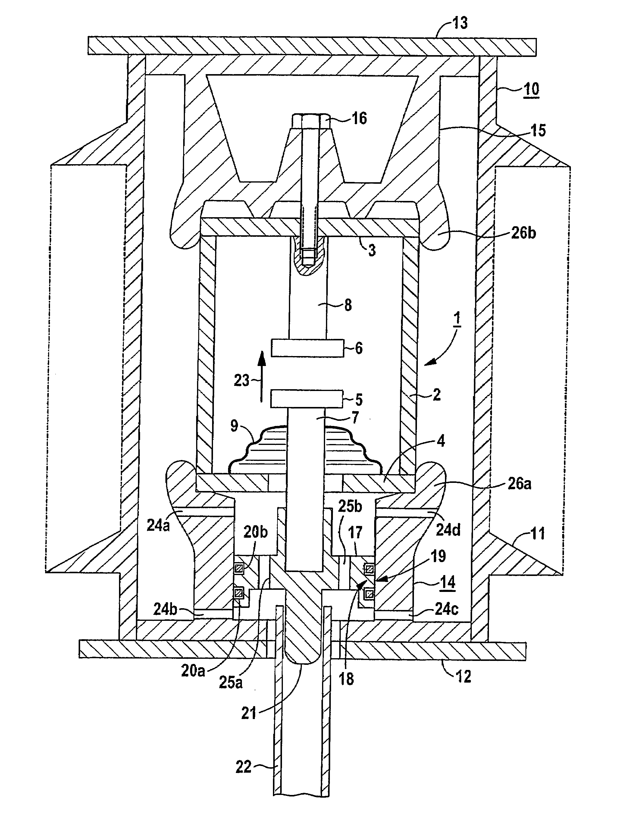
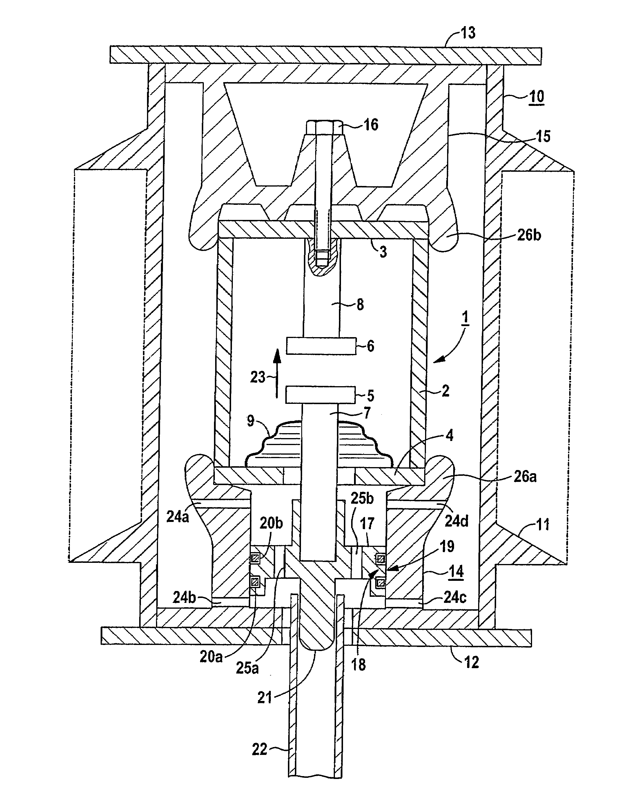
[0029]FIG. 1 shows a vacuum interrupter 1. The vacuum interrupter 1 is part of an interrupter unit of a switching pole of an electrical switch. The vacuum interrupter 1 has an insulating housing 2 and a first cover plate 3 and a second cover plate 4. Arranged in the interior of the vacuum interrupter 1 is a first contact piece 5 and a second contact piece 6. The first contact piece 5 and the second contact piece 6 form a switching contact. At the end of the first contact piece 5 which faces away from the switching contact, a first strut 7 is passed through the second cover plate 4 such that it can move. A second strut 8 bears the second contact piece 6 and positions it rigidly on the first cover plate 3. In order to pass the first strut 7 in a gas-tight manner through the wall of the vacuum interrupter 1, a bellows 9 is arranged between the first strut 7 and the second cover plate 4.

[0030]The vacuum interrupter 1 is arranged within an insulating housing 10. The insulating housing 10...


PUM


Abstract

According to the invention, heat generated inside a vacuum interrupter (1) is to be extracted, essentially by means of the pins (7, 8) of the contact pieces (5, 6) and, in order to improve the transmission of heat, a first slide contact surface (18) of a slide contact arrangement is provided on a pin (7), whereby the first slide contact surface (18) is arranged on a first section of a pin (7) which comprises an enlarged circumference relative to the remaining sections of the pin (7).

Description

[0001]This application is a national stage of International Application No. PCT / DE03 / 00583 which was published on Feb. 14, 2003, and which claims the benefit of priority to German Application No. 102 07 892.0 filed Feb. 20, 2002.TECHNICAL FIELD OF THE INVENTION[0002]The invention relates to a vacuum interrupter having a switching contact piece.BACKGROUND OF THE INVENTION[0003]A vacuum interrupter arrangement is disclosed, for example, in DE 35 29 386 A1. The first sliding contact face here is arranged on a thicker, first section and is electrically conductively connected to a second sliding contact face.[0004]A further arrangement is disclosed, for example, in the laid-open specification DE 196 03 157 A1. The vacuum interrupter described in the laid-open specification has a switching contact. The switching contact is essentially formed from two switching contact pieces, one of the switching contact piece being movable. The movable switching contact pieces has, at its end which faces...

Claims


Application Information

Patent Timeline
Patent Type & Authority Patents(United States)
IPC IPC(8): H01H33/66H01H1/58
CPCH01H1/5833H01H33/6606H01H2033/6613
Inventor CHYLA, THOMASHAGEN, JORGHOLLER, HELMUTMASCHER, KARL
Owner SIEMENS AG
Features
  • R&D
  • Intellectual Property
  • Life Sciences
  • Materials
  • Tech Scout
  • Unparalleled Data Quality
  • Higher Quality Content
  • 60% Fewer Hallucinations
Learn More