Camera monitoring system

a technology of camera monitoring and control system, applied in the field of camera control system, can solve problems such as no function, and achieve the effect of simple operation

Inactive Publication Date: 2006-10-03
CANON KK
View PDF29 Cites 79 Cited by
  • Summary
  • Abstract
  • Description
  • Claims
  • Application Information

AI Technical Summary

Benefits of technology

[0009]Another object of the present invention is to provide a camera control system which reflect change of hardware construction such as arrangement of cameras by simple operation by a user.
[0010]Further, another object of the present invention is to provide a camera control system which informs status of use and each user's access right by each camera in a real-time manner.

Problems solved by technology

However, in the conventional art, when a user wants to operate a camera, since there is no means for confirming whether or not the camera is actually in controllable status (i.e., any other user is not currently operating the camera, and the user has the operation right), the user merely has to try to remote-operate the camera.
Further, in the conventional art, there is no function for indicating status of use of each camera and its access right (right to see video images and operate them) by real time.

Method used


Image

  • Camera monitoring system
  • Camera monitoring system
  • Camera monitoring system

Examples


Embodiment Construction

[0040]Preferred embodiment of the present invention will now be described in detail in accordance with the accompanying drawings.

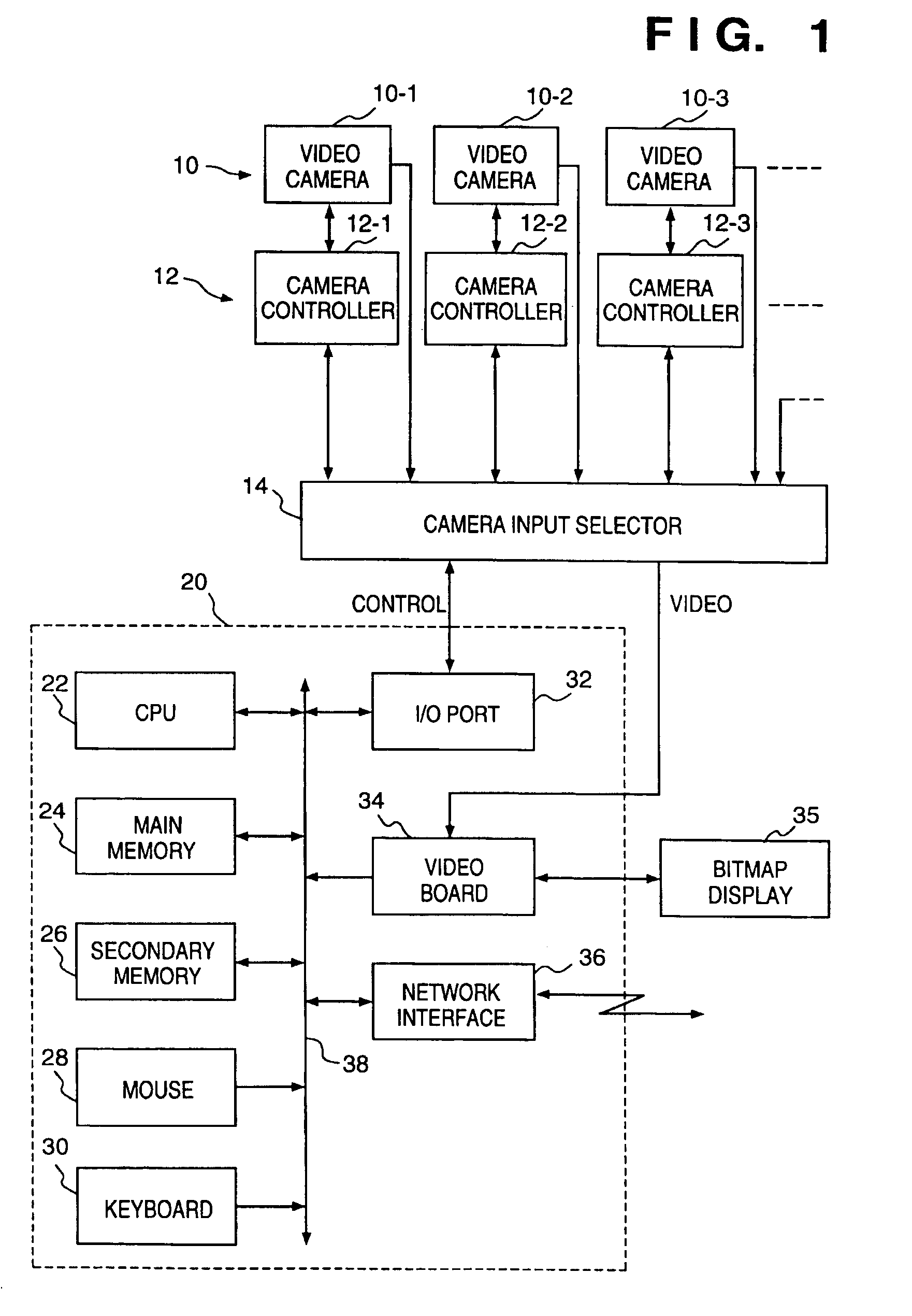
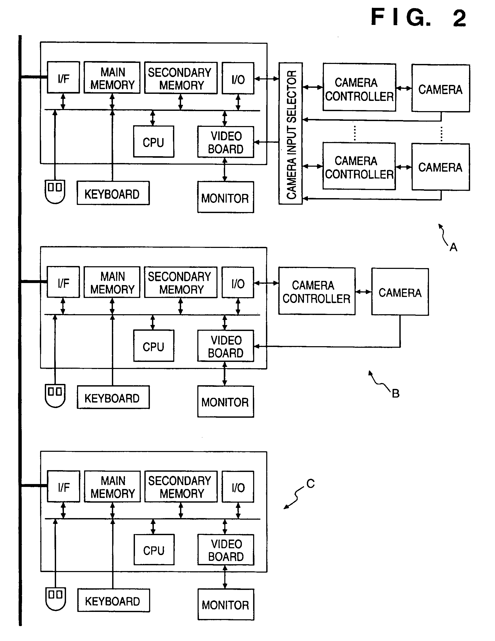
[0041]FIG. 1 is a block diagram showing the construction of a computer system according to an embodiment of the present invention, connected to a plurality of cameras as basic elements in the embodiment. A plurality of computers having the construction in FIG. 1 and a plurality of computers having a similar construction to FIG. 1 are mutually connected via a computer network.

[0042]In FIG. 1, reference numerals 10-1 to 10-3 denote video cameras; 12-1 to 12-3, camera controllers for directly controlling panning, tilting, zooming, focus adjustment and focal-length adjustment, in accordance with external camera control signals; and 14, a camera input selector for selecting one of the video cameras 10 and inputting the output signal(s) from the selected camera (normally a video signal, but in case of a video camera with a microphone, a video signal and an audio...


PUM


Abstract

A camera control system having a plurality of cameras connected to a network, enabling users to be informed of such as status of use of each camera and each user's access right in a real-time manner. The system, where one of cameras controllable via the network is selected and video-display of output from the selected camera and operation of the camera are controlled, has camera-status display device for real-time displaying the statuses of at least two cameras.

Description

BACKGROUND OF THE INVENTION[0001]Present invention relates to a camera control system and, more particularly to a camera control system that allows a single or plurality of users to remote-operate a plurality of cameras.[0002]A video transmission system which enables video transmission or communication by video and audio transmission between arbitrary two (or more) points, by constructing a network by arranging a number of cameras and computers in a building or the like, has been proposed.[0003]In this system, the user at an arbitrary point can remote-operate an arbitrary camera from the point, and / or display a video image from the camera on the display of a computer at the point.[0004]In the video transmission system enabling this remote-operation of an arbitrary camera, as the number of the cameras to be operated increases, it is necessary to easily know positions of the respective cameras.[0005]Generally, in a video conference using a plurality of computers connected via a networ...

Claims


Application Information

Patent Timeline
Patent Type & Authority Patents(United States)
IPC IPC(8): H04N5/232H04N7/18
CPCG08B13/1968H04N7/181
Inventor OYA, TAKASHIKAWAI, TOMOAKI
Owner CANON KK
Why Eureka
Try Eureka