Optical transceiver design and mechanical features

a technology of optical transceivers and mechanical features, applied in electromagnetic transmission, electrical equipment, transmission, etc., can solve the problems of inability to interface to backbone networks, high initial cost of methods, and inability to meet the needs of customers,

Inactive Publication Date: 2006-10-03
XYLON LLC
View PDF14 Cites 13 Cited by
  • Summary
  • Abstract
  • Description
  • Claims
  • Application Information

AI Technical Summary

Problems solved by technology

However, many homes and offices do not have a practical solution to interface to these backbone networks.
Consequently, direct attachment of potential customers to these backbone networks remains very expensive.
However, both of these methods incur significant up-front costs before any revenue can be realized.
In the case of buried or aerial fiber, these costs are associated with obtaining rights-of-way for the cable runs, and installing the cable by burying or hanging.
In the case of a microwave system, these up front costs come not only from the cost associated with the microwave repeater equipment, but also from the costs associated with obtaining rights to the suitable portion of the spectrum.
Therefore, system developers and integrators have sought long and hard to find suitable solutions to this “last mile” problem.
Additionally, after initial installation has been completed, it may become necessary to quickly replace a damaged or dysfunctional node with a replacement node.

Method used


Image

  • Optical transceiver design and mechanical features
  • Optical transceiver design and mechanical features
  • Optical transceiver design and mechanical features

Examples


Embodiment Construction

[0030]The following presents a detailed description of embodiments of the present invention. However, the invention can be embodied in a multitude of different ways as defined and covered by the claims.

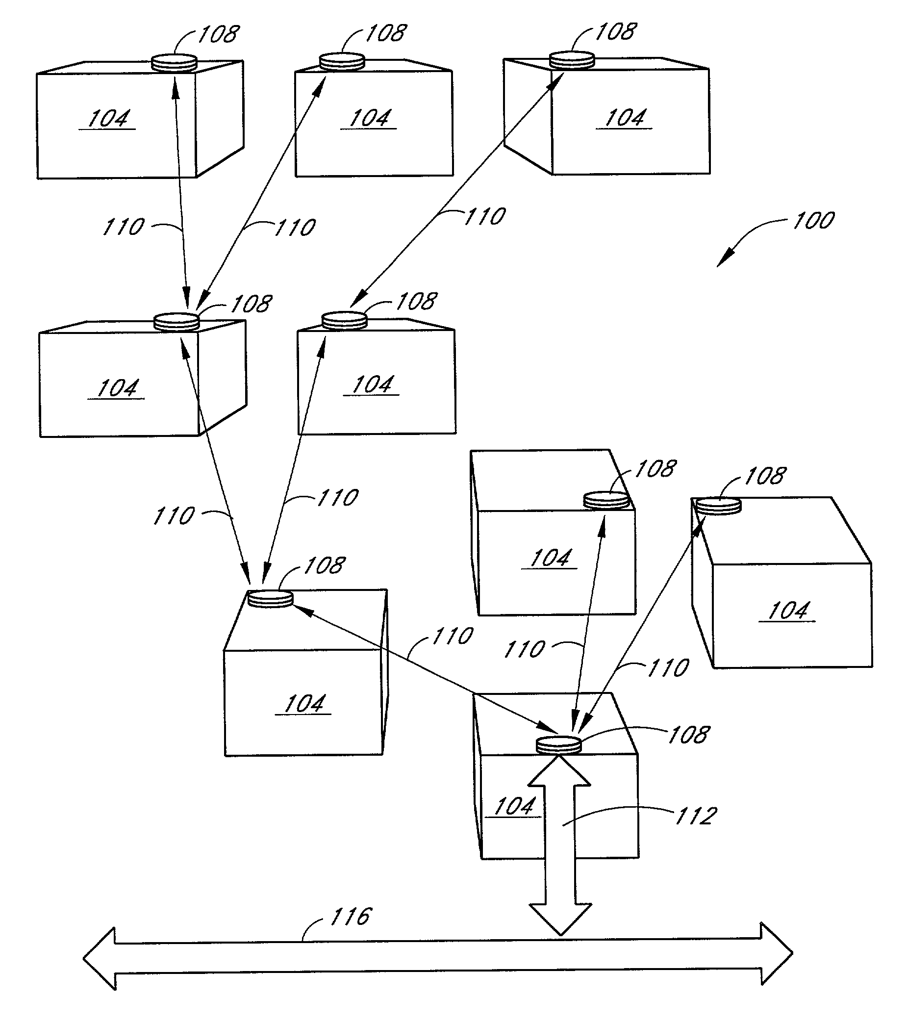
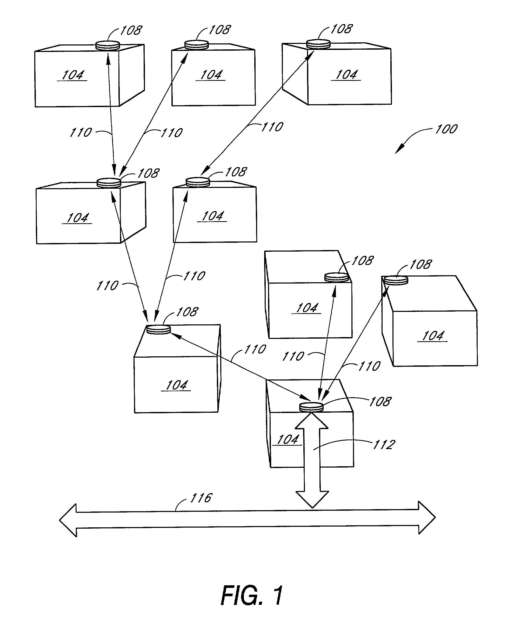
[0031]FIG. 1 is a diagram illustrating an example communication network 100. The communication network 100 can include a plurality of nodes 108, interconnected by communication links 110. The network nodes 108 are disposed on facilities 104. Although only one node 108 is provided per facility in the example illustrated in FIG. 1, more than one node 108 can be provided at one or more of the facilities 104, depending on the communication requirements, and also, perhaps, depending on the particular facility.

[0032]Facilities 104 can be buildings, towers, or other structures, premises, or locations. Facilities 104 can, for example, be homes or offices to which it is desirable to interface one or more backbone networks of one or more common carriers or service providers. In this example emb...


PUM


Abstract

A node for use in a wireless communication network that facilitates alignment of the node with other nodes in the network and a method for aligning the node. The node includes mounting fixtures that enables the mounting of GPS receivers and a tiltmeter to obtain position and bearing information for the node. The node contains alignment features that enable the positioning of an optical transmitter / receiver pair in the node using the data obtained from the GPS receivers and tiltmeter.

Description

[0001]The benefit under 35 U.S.C. § 119(e) of the following U.S. provisional applications entitled FREE SPACE ALIGNMENT BY GPS, Ser. No. 60 / 204,361, filed May 16, 2000, METHOD AND SYSTEM FOR ENCLOSING AN OPTICAL COMMUNICATIONS TERMINAL, Ser. No. 60 / 212,038, filed Jun. 16, 2000, and OPTICAL TRANSCEIVER DESIGN AND MECHANICAL FEATURES, Ser. No. 60 / 242,220, filed Oct. 20, 2000, is hereby claimed and which are hereby incorporated by reference.BACKGROUND OF THE INVENTION[0002]1. Field of the Invention[0003]This invention relates to free-space optical communication systems, and in particular, to improved mechanical features that enable alignment of the optical transceiver nodes.[0004]2. Description of the Related Art[0005]Over the last several years there has been tremendous growth in the deployment of fiber-optic facilities by telecommunications carriers such as Regional Bell Operating Companies (RBOCs), cable carriers, and Competitive Local Exchange Carriers (CLECs). Deployment of these ...

Claims


Application Information

Patent Timeline
Patent Type & Authority Patents(United States)
IPC IPC(8): H04B10/00H04B10/10
CPCH04B10/1125
Inventor BLOOM, SCOTT HARRISKIRSTEN, OSKAR HAMMERALWAN, JAMES J.
Owner XYLON LLC
Why Eureka
Try Eureka