System component having a braking spring

a technology of braking spring and system component, which is applied in the direction of water treatment parameter control, mechanical equipment, knitting, etc., can solve the problems of faulty positioning, easy soiling of intermediate spaces, and prone to slipping, so as to improve flexibility, the width of such a cut is preferably greater, and the free motion of the tongue is satisfactory.

Active Publication Date: 2006-10-10
GROZ BECKERT KG
View PDF14 Cites 32 Cited by
  • Summary
  • Abstract
  • Description
  • Claims
  • Application Information

AI Technical Summary

Benefits of technology

[0009]This object is achieved with the system component according to the invention includes a shank having flanks which are essentially parallel to one another. In at least one of the flanks a recess is formed, in the region of which a spring or resilient tongue is arranged which forms a one-piece, i.e., integrated, part of the shank. In this manner the spring tongue has a thickness which is less than the thickness of the shank. The spring tongue is held in a simple manner captive on the system component. Manufacturing is simple and reliable. By virtue of the tongue thickness which is reduced relative to the thickness of the system component proper, the tongue, even if it has only a short length, may be flexible to a high degree. In particular, flat spring characteristics may be achieved. In this manner a good tolerance equalization may be provided also as far as the width of the guide groove is concerned in which the system component is positioned. As compared to free-standing spring tongues, whose thickness corresponds to the shank thickness, flatter spring characteristics may be obtained.
[0011]The thickness of the spring tongue is preferably significantly less than the thickness of the system component defined by the distance between its flanks. For this purpose it is sufficient to provide the recess solely at one side of the system component. It is, however, also feasible to form recesses on both sides or flanks of the system component, in which case the recesses together bound a thin wall portion serving to form the spring tongue. The spring tongue is set free by the provision of a U-shaped cut. The width of such a cut is preferably greater than the thickness of the tongue; this has manufacturing advantages and provides for a satisfactory free motion of the tongue.
[0012]The spring tongue may be bent into or away from the recess. In either case the tongue may be tapered toward its end both in its thickness and in its height for improving its flexibility and to avoid the concentration of its bending movement solely in the region of its root. A tapering of the tongue thickness may be obtained by providing the recess with an increasing depth toward the spring tip.

Problems solved by technology

Further, a bending of the entire knitting tool may result in a faulty positioning of the latter.
The intermediate spaces, however, are prone to soiling.

Method used


Image

  • System component having a braking spring
  • System component having a braking spring
  • System component having a braking spring

Examples


Embodiment Construction

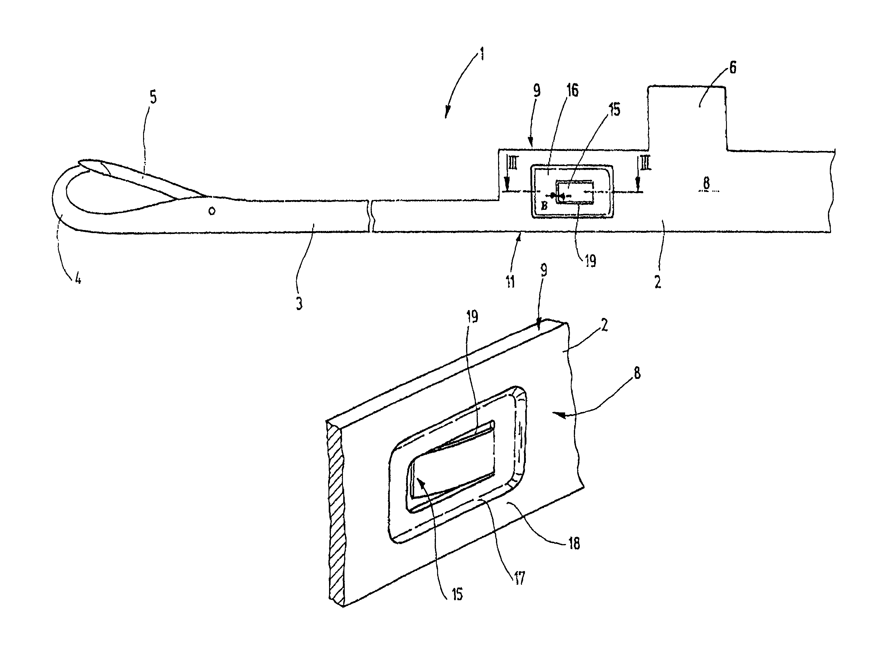
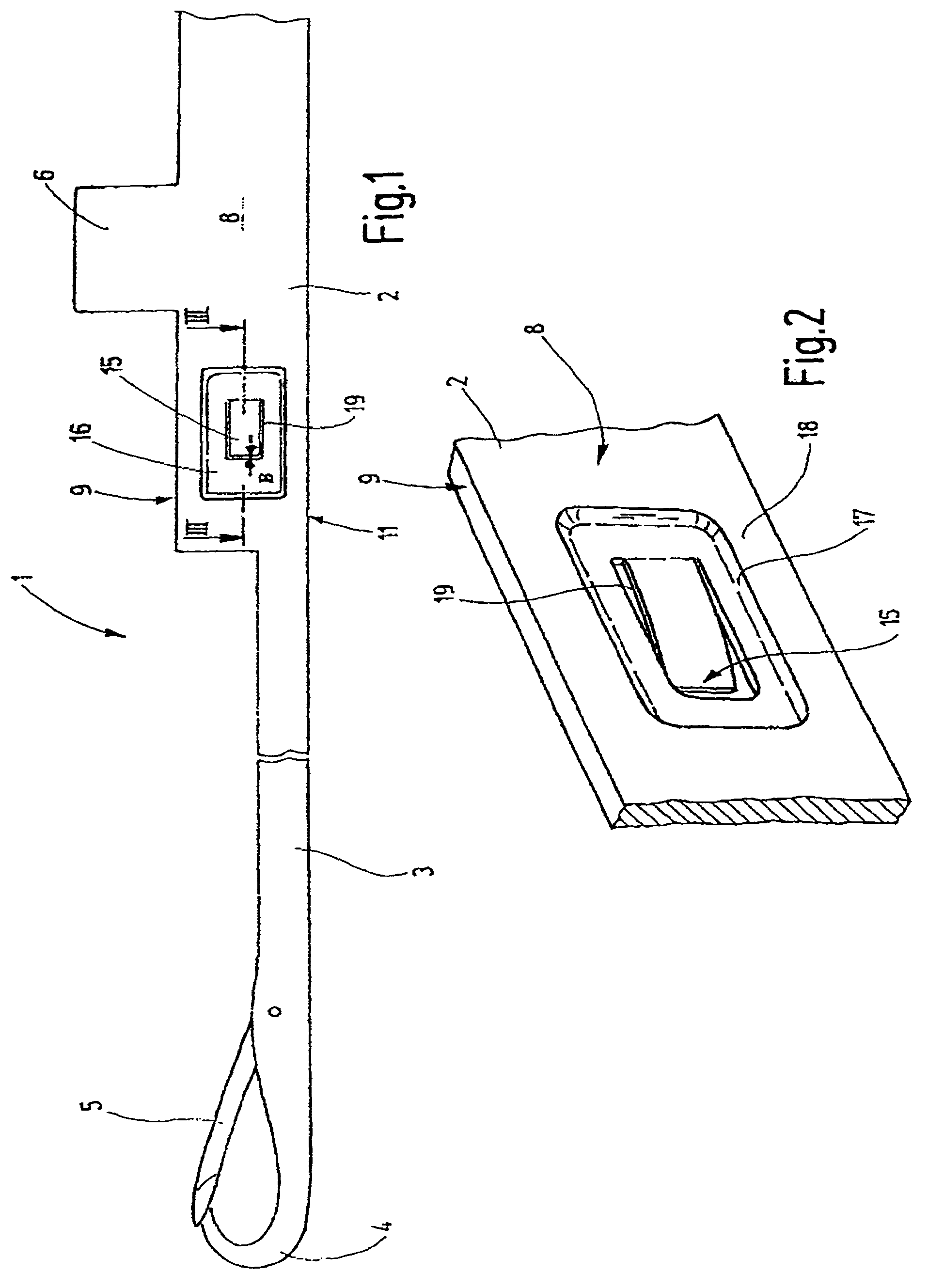
[0025]FIG. 1 shows a knitting needle 1 belonging to a knitting system and constituting a component thereof. The knitting needle 1 has a shank 2 which at one end changes into a shank region 3 of lesser height. At its end the shank region 3 carries a hook 4. If required, a pivotally supported latch 5 may be associated with the hook 4. At least one butt 6, cooperating with a drive, such as a cam, is formed on the shank 2. The shank 2 is a flat part having a rectangular cross section.

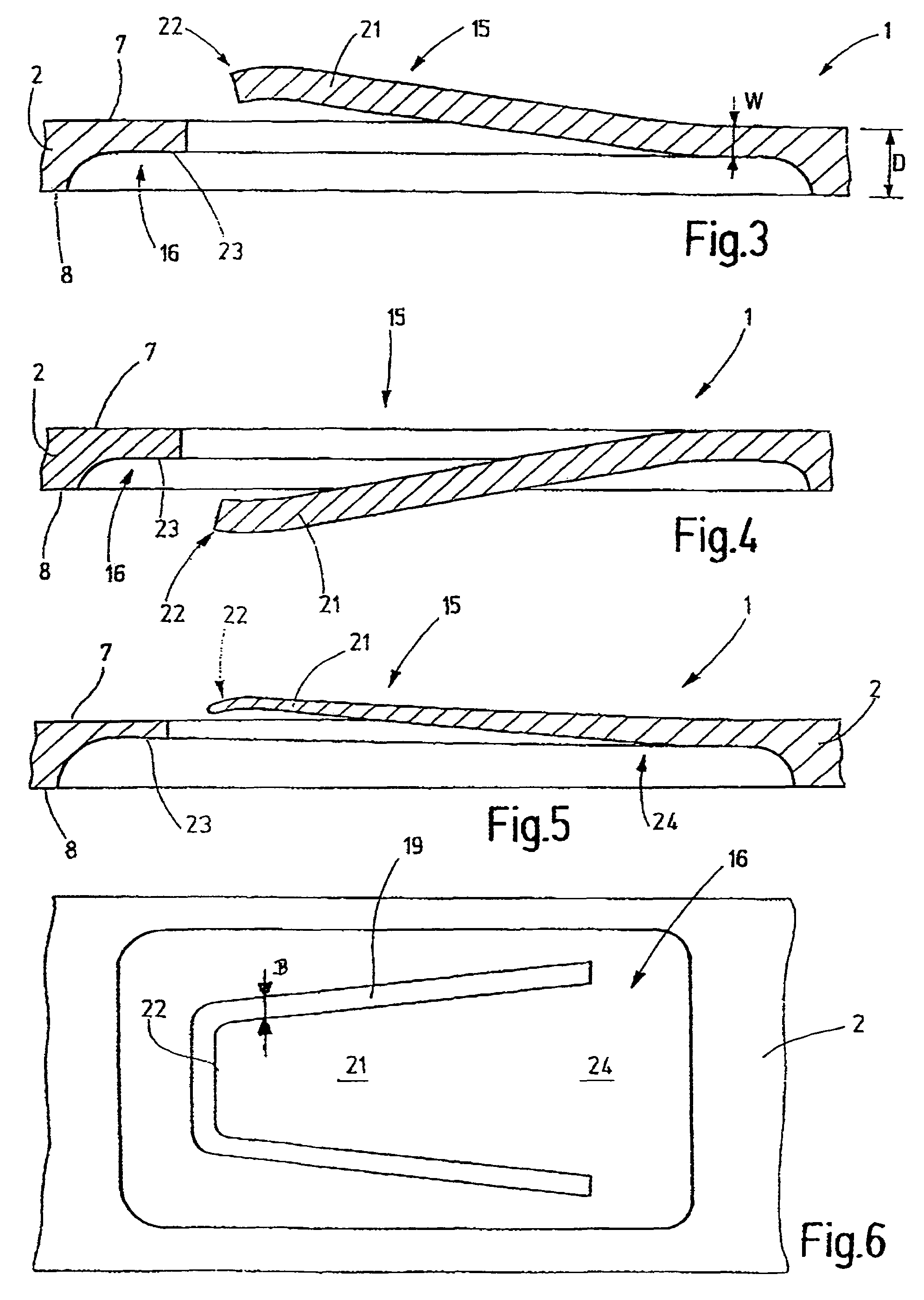
[0026]As illustrated in FIG. 3, the shank 2 has two, preferably planar flanks 7, 8 which, as shown in FIG. 1, extend from the upper needle side 9 to the needle back 11.

[0027]A braking spring 15 is formed on the shank 2 for supporting the knitting needle 1 in a needle groove 12, as shown, for example, in FIG. 8, in such a manner on the side surfaces 13, 14 that the knitting needle 1 can be moved in the axial direction with a certain hindrance. For this purpose, at a suitable location of the shank 2, for exam...


PUM


Abstract

A knitting tool (1) is provided with a braking spring (15) formed on the knitting tool as a one-piece member thereof. The braking spring has a thickness (W) which is less than that of the knitting tool (1), whereby the braking spring (15) may yield to a great extent and has a soft spring characteristic. Such a result may be achieved even with short spring lengths, whereby dimensional deviations of the spring have only a slight effect on the spring force. The structure is only slightly prone to soiling. The knitting tool may be manufactured in a simple manner.

Description

CROSS REFERENCE TO RELATED APPLICATION[0001]This application claims the priority of European Patent Application No. 04 009 397.3, filed on Apr. 21, 2004, the subject matter of which, in its entirety, is incorporated herein by reference.FIELD OF THE INVENTION[0002]The invention relates to a system component forming part of a knitting system of a loop-forming machine. Such a component may be, for example, a machine knitting needle, a selecting component, a sinker or the like.BACKGROUND OF THE INVENTION[0003]System components of knitting machines are, as a rule, longitudinally slidably guided in grooves, such as needle grooves of a needle cylinder or similar slot-like guides. The longitudinal motion of the system component is generated by a suitable drive, such as a cam which moves relatively to a projection (termed as a butt) of the system component. The butt extends into a corresponding groove which has a shape corresponding to the driven motion of the system component. Between the c...

Claims


Application Information

Patent Timeline
Patent Type & Authority Patents(United States)
IPC IPC(8): D04B35/04D04B15/68D04B35/02
CPCD04B35/04C02F11/00F17D1/088C02F2103/005C02F2209/42
Inventor BRAUN, JOCHENHENNIG, UWE
Owner GROZ BECKERT KG
Why Eureka
Try Eureka