Device and method for manufacturing a fiber-reinforced composite fuselage shell for an aircraft

a composite fuselage shell and fiber-reinforced technology, applied in the direction of domestic articles, sustainable transportation, other domestic articles, etc., can solve the problems of excessive pressing and achieve the effect of reliable and simple manufacturing

Active Publication Date: 2014-12-16
AIRBUS OPERATIONS GMBH +1
View PDF11 Cites 1 Cited by
  • Summary
  • Abstract
  • Description
  • Claims
  • Application Information

AI Technical Summary

Benefits of technology

[0010]An aspect of the present invention relates to a device and a corresponding method for manufacturing a fiber-reinforced composite fuselage shell for an aircraft, which fuselage shell is suitable for efficient, reproducible, series production and allows reliable and simple manufacture of strongly curved fuselage shells.
[0012]The method according to an aspect of the invention provides an advantage, in particular, in that positioning of the stringers, placement of the auxiliary materials, and the application of the vacuum foil no longer need to be carried out on the component itself, but can be carried out on a separate rigging device. Consequently, the actual laminating-bonding device no longer needs to be occupied for the duration of rigging, because the process of transferring the stringer and the vacuum construction accounts for only a comparatively small component of the manufacturing time. All the manufacturing steps, namely rigging and placing the half shell to be constructed into the laminating-bonding device can occur in parallel. Positioning the stringers takes place by simple insertion into the prepared depressions of the device according to the invention, in which depressions the stringer is then neatly guided. It is no longer necessary, as has been the case up to now, to place the vacuum foil in strong folds; instead, said foil is either deep-drawn into the prepared depressions of the mold surface or is correspondingly pre-draped and subsequently subjected to a vacuum. With the use of the longitudinally adjustable actuators, and the resulting change in the mold surface it is possible, in particular, to manufacture fuselage shells with strong opening angles by means of the rigging device. Thus the pronounced undercuts, which are present in the case of fuselage shells with strong opening angles, no longer hinder demolding, and precise positioning is nevertheless possible thanks to the mold surface that can be adjusted according to the invention. In the case of an already cured stringer it is even possible for form pieces to be done without, either partly or entirely. In the case of the so-called co-curing method the outer geometry of the forming supporting elements no longer depends on the undercut angle; said supporting elements can thus be greatly simplified. In addition, the solution according to the invention makes it possible to press a sealing seam, which us usually present in vacuum constructions, against the laminating-bonding device. Adjusting the actuators could, if required, also take place to a different extent, because usually a larger offset gap is necessary at the side flanks than in the region of the middle of the fuselage shell. The contact pressing force of the stringers against the component during the transfer process can be set with precision, so that excessive pressing can be excluded. Excessive pressing would, for example, be possible in the case of large and very heavy devices as a result of unintended bending of the rigging device. In this case a heavy load would be resting on the stringer, which could result in damage.
[0015]According to another additional aspect that improves the invention, it is possible to interconnect in an airtight manner the individual mold channels along the longitudinal edges by means of an elastic belt as a flexible intermediate element. Consequently, the required flexibility of the device according to the invention in radial direction can be produced in a simple manner.
[0018]According to a further measure that improves the invention it is proposed for the cavity region of the mold channel to comprise several positioning sections that are arranged so as to be spaced apart from each other and that correspond to the desired position of the stringer to be inserted. Thus, at the position of the positioning sections the cross section of the mold channel is preferably reduced by a few millimeters down to the desired external dimensions of the stringer to be inserted in this location. At this position the stringer is then guided in a simple manner and positioned precisely. In addition, in regions of the positioning sections it is also possible to affix, preferably to the rear, magnets or the like for affixing the stringers.

Problems solved by technology

Excessive pressing would, for example, be possible in the case of large and very heavy devices as a result of unintended bending of the rigging device.
In this case a heavy load would be resting on the stringer, which could result in damage.

Method used


Image

  • Device and method for manufacturing a fiber-reinforced composite fuselage shell for an aircraft
  • Device and method for manufacturing a fiber-reinforced composite fuselage shell for an aircraft
  • Device and method for manufacturing a fiber-reinforced composite fuselage shell for an aircraft

Examples


Embodiment Construction

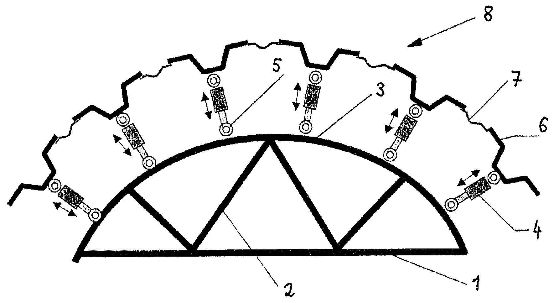
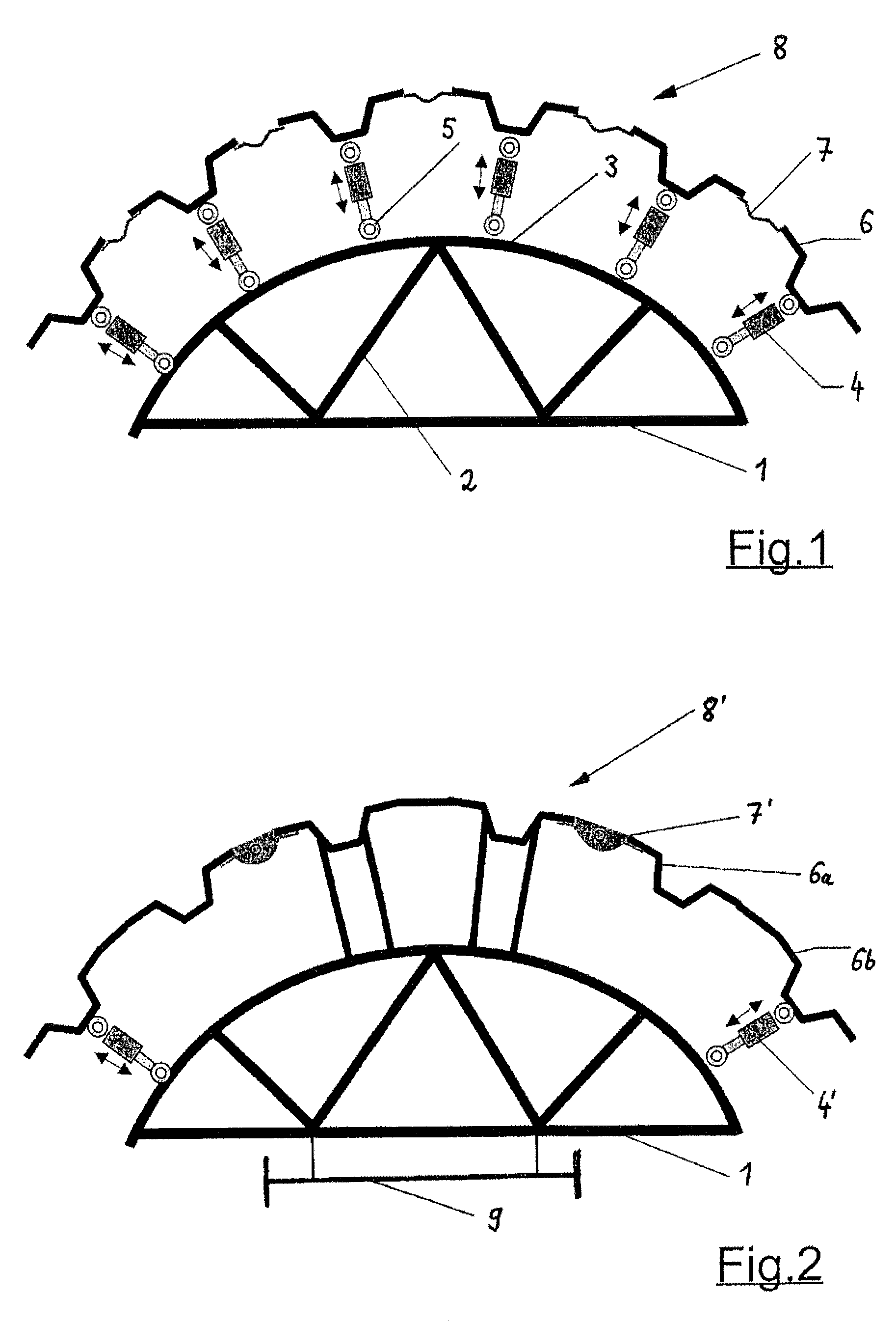
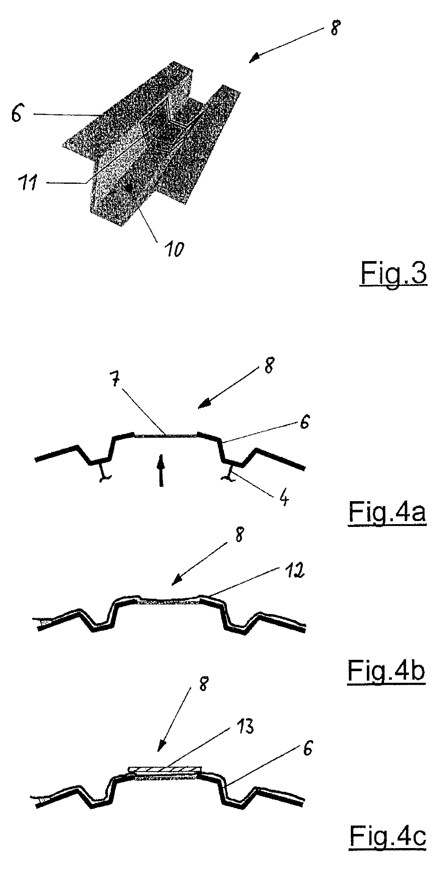
[0037]According to FIG. 1 a rigging device essentially comprises a base frame 1 for forming a curved mounting surface 3 and for manufacturing a rigid substructure. Several radially-outward extending actuators 4 have been affixed to the mounting surface 3. On the side of the mounting surface 3 the actuators 4 have been hingeably installed by way of joints / elongated holes 5 and in each case at their distal ends comprise mold channels 6 for receiving stringers (not shown in detail) of the fuselage shell. The individual mold channels 6 are interconnected with pliable / elastic intermediate elements 7 in such a manner that overall a mold surface 8 forms that is closed so as to be vacuum tight.

[0038]In this exemplary embodiment the flexible intermediate elements 7 are designed as elastic belts.

[0039]In the exemplary embodiment shown in FIG. 2, several adjacent mold channels 6a, 6b are rigidly interconnected and are hinged to the base frame 1 by way of a flexible intermediate element 7′ desi...


PUM

PropertyMeasurementUnit
diameteraaaaaaaaaa
strengthaaaaaaaaaa
lengthsaaaaaaaaaa

Abstract

A device and a method for manufacturing a fiber-reinforced fuselage shell for an aircraft, which fuselage shell for the purpose of reinforcement comprises several stringers that are spaced apart from each other, wherein the device includes a base frame comprising several supporting walls of different lengths for forming a curved mounting surface for the fuselage shell to be manufactured, wherein several actuators that extend radially outwards and that are longitudinally adjustable are affixed to the mounting surface, at the distal ends of which actuators in each case mold channels for receiving the stringers are attached, which mold channels are interconnected by means of flexible intermediate elements and / or further mold channels for forming a vacuum-tight closed mold surface.

Description

CROSS-REFERENCE TO RELATED APPLICATIONS[0001]The present application is a continuation of International Application No. PCT / EP2010 / 069052, filed on Dec. 7, 2010, which claims the benefit of the filing date of German Patent Application No. 10 2009 056 978.2, filed Dec. 7, 2009 and of U.S. Provisional Application No. 61 / 267,222, filed Dec. 7, 2009, the disclosures of which are incorporated herein by reference in their entireties.TECHNICAL FIELD[0002]The present invention relates to a device and to a method for manufacturing a fiber-reinforced composite fuselage shell for an aircraft, which fuselage shell for the purpose of reinforcement comprises several stringers that are arranged so as to be spaced apart from each other, with the device comprising a base frame for forming a curved mounting surface for the fuselage shell to be manufactured.[0003]The field of application of the present invention predominantly relates to aircraft construction. In particular, wide-bodied commercial airc...

Claims


Application Information

Patent Timeline
Patent Type & Authority Patents(United States)
IPC IPC(8): B29C70/44B29D99/00B29C65/00B29C70/32B29L31/30B29C33/48B29C47/00
CPCB29D99/001Y02T50/43B29C33/485Y02T50/433B29C70/32B29C70/443B29L2031/3082B29D99/0014B29C33/307Y02T50/40
Inventor BARLAG, CARSTENSTEIGER, CHRISTIANDESCHAUER, NIELS
Owner AIRBUS OPERATIONS GMBH
Why Eureka
Try Eureka