The pipe cable ring clamb and the series of pipe cable ring clamp installation apparatuses

a technology of cable ring clamping and pipe cable, which is applied in the direction of mechanical equipment, instruments, optical elements, etc., can solve the problems of difficult to use solutions for pipes smaller than 200 mm in diameter, difficult to ensure the reliability of the clamping to a particular location, and complex mounting methods of the brackets, etc., to achieve reliable, reduce the lightness of the pipe, and improve the effectivity

Pending Publication Date: 2021-08-12
GWB CZ SRO
View PDF0 Cites 2 Cited by
  • Summary
  • Abstract
  • Description
  • Claims
  • Application Information

AI Technical Summary

Benefits of technology

[0011]The present invention achieves a new and higher effectivity in that the pipe cable ring clamp does not overly reduce the lightness of the pipe and is thus also usable in pipes of smaller diameters, is reliable and simple to manufacture and ther

Problems solved by technology

The mounting method of the brackets is very complex and the reliability of their attachment to a particular location is very problematic, among other things due to the apparently weak expansion force of the brackets given only by the pre-tension of the material used.
However, this solution cannot be used for pipes smaller than 200 mm in diameter.
The amount of the pressing force holding the fastener in the appropriate place is questionable, further, this design considerably reduces the inner diameter of the pipe, and the dismantling thereof, or re-installation of the cables is virtually impossible.
These solutions are unsuitable for small pipe diameters, because they greatly reduce its usable diameter, and in these cases, the addition of another cable or its uninstallation or reinstallation is very problematic, since the foam coating must first be removed and only then can these operations be performed, which basically means a completely new installation.
However, such a solution is usable and feasible only when

Method used


Image

  • The pipe cable ring clamb and the series of pipe cable ring clamp installation apparatuses
  • The pipe cable ring clamb and the series of pipe cable ring clamp installation apparatuses
  • The pipe cable ring clamb and the series of pipe cable ring clamp installation apparatuses

Examples


Embodiment Construction

OF PREFERRED EMBODIMENTS

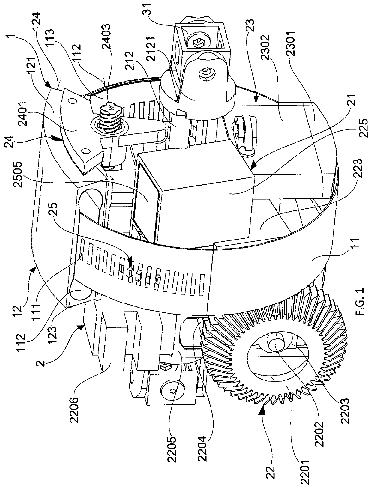
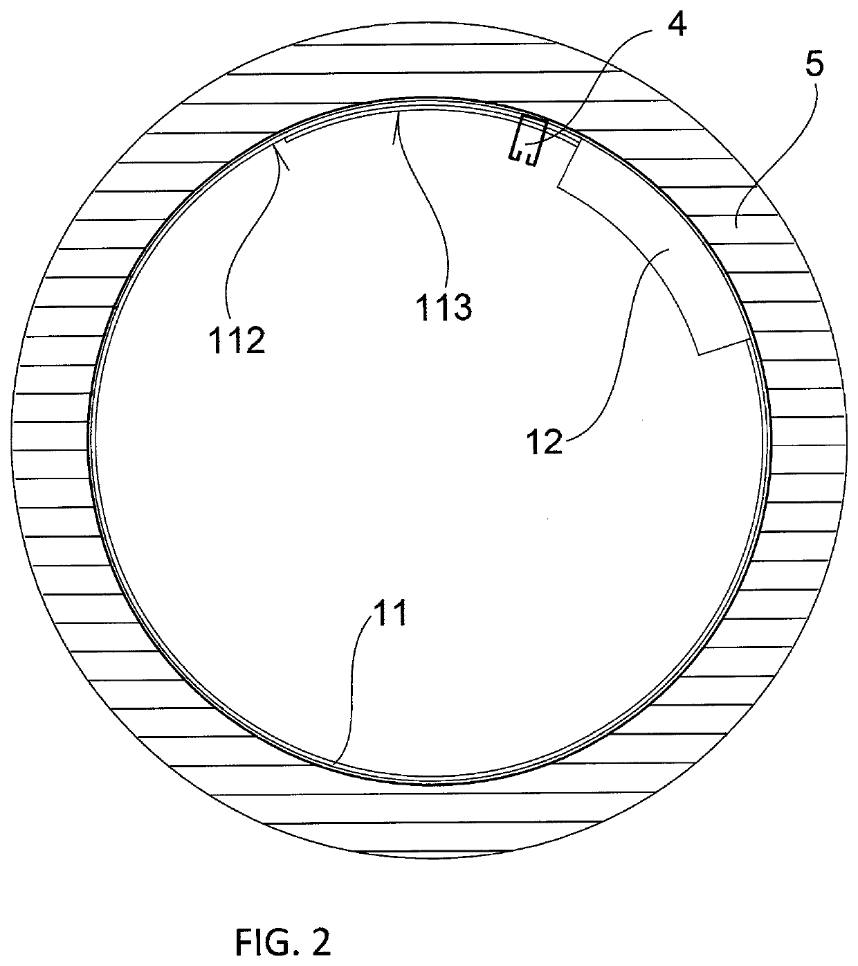
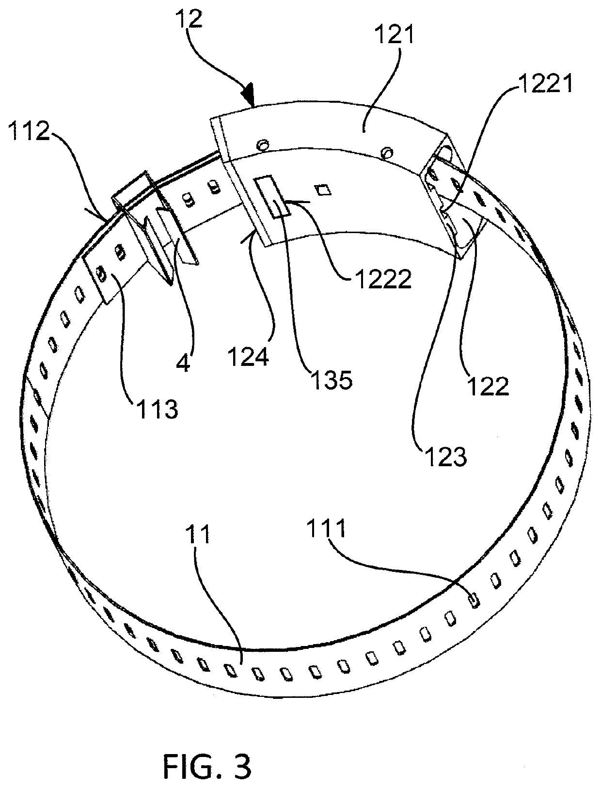
[0028]The pipe cable ring clamp 1 as pictured in FIG. 1 is attached to the apparatus 2 for its installation. In the basic embodiment shown in FIGS. 2 and 3, the pipe cable ring clamp 1 is formed by a coiled clip band 11 and a strap lock 12, in the body of which the clip band 11 is fixed by the end of its outer coil 112, the inner coil 113 of the clip band 11 is slidably mounted in the strap lock 12 body. The clip band 11 is provided with regular transverse slots 111 in regular intervals. The cross-section of the strap lock 12 is a vertical plane perpendicular to the longitudinal axis of the apparatus 2, in the form of an annular segment, where the radius of its outer curvature corresponds to the inner radius of the pipe 5 in which the pipe cable ring clamp 1 is to be installed. The strap lock 12 shown in FIGS. 4 and 5 is formed by the lock body 121 provided with the inner cavity 122 which is open towards the lock face 123 over its entire cross-section and is ...


PUM


Abstract

The pipe cable ring clamp (1) comprising a coiled flat clip band (11) provided with transverse slots (111) on which at least one cable holder (4) is attached and comprising the outer coil (112) and the inner coil (113), and a strap lock (12) in which the clip band (11) is fastened, wherein the inner coil (113) of the clip band (11) is slidably mounted in the strap lock (12) and the strap lock (12) includes lock springs (139) coupled to the inner coil (113) of the clip band (11). The lock springs (139) are received in the strap lock (12) along the edges of the clip band (11) outside the contour of its perpendicular projection into the cylindrical surface of the pipe (5), the lock springs (139) are via the inner coil (113) of the clip band (11) coupled by the movable member (127) slidably mounted in the strap lock (12), wherein the movable member (127), on its end opposite to the rear wall (125) of the strap lock (12) is provided with spring stops (129) on which the lock springs (139) rest with one end thereof, while the other ends rest on the rear wall (125) of the strap lock (12) and wherein the movable member (127) is coupled to the inner coil (113) of the clip band (11) by a pusher tongue (133) in the pivotally mounted movable member (127), wherein the movable member (127) is adapted both to fix it in the rear position while compressing the lock springs (139) and to release it using the latch (135) slidably mounted in a vertical direction in the body of the movable member (127). It is also the basis of the series of pipe cable ring clamp installation apparatus invention.

Description

FIELD OF THE INVENTION[0001]The present invention falls within the field of cable and conduit installation and relates to the design of the cable clamp and the series of apparatuses for its installation.BACKGROUND OF THE INVENTION[0002]A number of solutions are known for the installation of fiber optic cables in a sewer network, for example, the JPH05272664 file describes the embodiment of cable fixation in pipes by means of pre-locked horseshoe-shaped holders made of flat material and fixed along the pipe walls with the open portion facing down. These holders are held against the wall of the pipe only by the force of their pre-tensioning and are set into the pipe by inverted T-shaped segments detachably secured by means of locks to the holders on the ends of their arms, which pull the horseshoe shape to a diameter smaller than the diameter of the pipe and which are connected with a pull cord. Upon delivery of the holders to the designated location in the pipe, the T-segments are di...

Claims


Application Information

Patent Timeline
IPC IPC(8): G02B6/44G02B6/50
CPCG02B6/4459G02B6/508G02B6/50G02B6/54F16L3/14F16L3/133F16L55/18H02G3/32G02B6/4471
Inventor NAJMAN, MICHAL
Owner GWB CZ SRO
Why Eureka
Try Eureka