Vehicular lamp and method of manufacturing same

a technology of vehicle lamps and manufacturing methods, which is applied in the field of vehicle lamps, can solve the problems of deteriorating lamp appearance, complicated metal molding structure employed for forming lenses with laser beam receiving surfaces configured to protrude beyond the outer surface of seal legs, and improve the appearance of lamps. , the effect of efficient projection

Active Publication Date: 2006-10-10
KOITO MFG CO LTD
View PDF5 Cites 4 Cited by
  • Summary
  • Abstract
  • Description
  • Claims
  • Application Information

AI Technical Summary

Benefits of technology

[0011]According to an embodiment of the present invention, the laser welded surface is formed so as not to protrude beyond the outer surface of the lens. This may reduce the dimensions of the dark portion around the periphery of the lens when seen from the front. Thus the outer appearance of the lamp may be improved. Further, as the laser welded surface is inclined with respect to the direction where the lens is mounted on the lamp body, the laser-welded area may be expanded. Accordingly, welding performance may be enhanced.
[0012]According to an embodiment of the present invention, the angle of the projected laser beam with respect to the outer surface of the lens is adjusted such that the laser beam is projected in the direction perpendicular to the inclined abutment surface. Thus, the laser beam can be efficiently projected to the abutment surface without the laser beam receiving surface protruded outward. Accordingly, this makes it possible to make desirable laser welding.

Problems solved by technology

Further, when the welded surface between the lens and the lamp body is seen from the front through the lens, it appears dark.
Because width dimensions of the laser welded surface (i.e., dimensions in a direction of the thickness of the seal leg) enlarges due to forming the laser beam receiving surface, the dark portion with larger width come out from the outer edge of the lens, and thereby the appearance of the lamp deteriorates.
Further, a metal molding structure employed for forming the lens having the laser beam receiving surface configured to protrude beyond the outer surface of the seal leg may be complicated.
Thus, this creates rising cost.

Method used


Image

  • Vehicular lamp and method of manufacturing same
  • Vehicular lamp and method of manufacturing same
  • Vehicular lamp and method of manufacturing same

Examples


Embodiment Construction

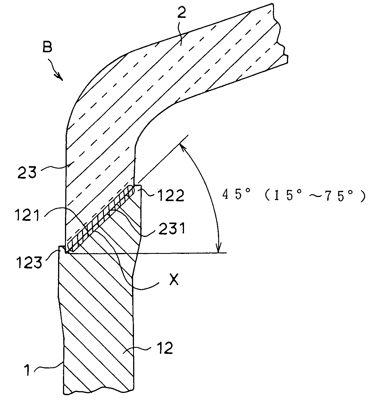
[0024]In the preferred embodiment of the present invention, the lens includes a seal leg portion with a substantially uniform thickness which extends in a direction where the lamp body and the lens are brought into abutment along an edge portion of the lens, and an end surface of the seal leg portion serves as the abutment surface. The abutment surface may be formed within a range of the thickness of the seal leg portion. Thus, the aesthetic appearance of the lamp improves. Further, the lamp body includes a tapered flange portion, which protrudes outward along the outer surface thereof, configured to gradually reduce its thickness as it goes outward, and a top surface of the flange portion serves as the abutment surface. Advantageously, the flange portion allows abutting performance between both to be enhanced upon deformation of the flange portion causing by abutment of the lens on the lamp body, and accordingly, the welding performance improves.

[0025]An embodiment of the present i...


PUM

PropertyMeasurementUnit
angleaaaaaaaaaa
angleaaaaaaaaaa
refractive indexaaaaaaaaaa

Abstract

A vehicular lamp includes a lamp source, a lamp body accommodating the lamp source, and a lens attached to the lamp body. The lamp body has an abutment surface on the top portion of a peripheral wall, which is configured to rise in a direction of an optical axis of the light source along a peripheral edge of the lamp body. The abutment surface of the lamp body is configured to incline to the optical axis. Similary, the lens has an abutment surface corresponding to the abutment surface of the lamp body along a peripheral portion of the lens. In this case, the abutment surface of the lens is configured within the dimention of an outer surface of the lens so as not to protrude over the outer surface. The abutment surfaces of the lamp body and the lens are integrally jointed together by laser walding.

Description

BACKGROUND OF INVENTION[0001]1. Field of the Invention[0002]The present invention relates to a vehicular lamp with a lens attached to a lamp body by laser welding and a method of manufacturing same.[0003]2. Background Art[0004]A vehicular lamp, such as a headlamp for a motor vehicle, is configured to dispose a bulb as a light source and a reflector in a lamp chamber, which is formed by attaching a lens to a front opening of a lamp body. For a configuration in which the lens is attached to the front opening of the lamp body, the prior art has used a laser welding method or the like. Patent Document 1 discloses a laser beam receiving surface is configured in a flange-like shape to protrude outwardly so that the receiving surface can receive a laser beam coming from an oblique direction with respect to a direction where the lens is mounted on the lampbody, which passes through the flange-like shaped portion of the lens.[0005]Specifically, as shown in FIG. 10, the laser welding is appli...

Claims


Application Information

Patent Timeline
Patent Type & Authority Patents(United States)
IPC IPC(8): F21V31/00B29C65/16F21S8/10F21V17/00F21W101/10
CPCB29C65/1635B29C65/7841B29C66/1224B29C66/1226F21S48/255B29C65/169B29C66/1312B29C66/1162B29C66/1222B29C66/12261B29C66/12441B29C66/12449B29C66/12463B29C66/12464B29C66/12469B29C66/1282B29C66/12841B29C66/1286B29C66/131B29C66/542B29C65/1677B29C66/116B29L2031/747B29L2031/30B29C66/8322B29C66/7392B29C66/73921B29K2995/0027B29C66/73343F21S43/51B29C66/14
Inventor MATSUNAGA, CHIHARUSUZUKI, MICHIHIKOSUGIYAMA, FUJIHIKOYAMAZAKI, KAZUHIRO
Owner KOITO MFG CO LTD
Why Eureka
Try Eureka