Supercharge Your Innovation With Domain-Expert AI Agents!

Multi-beam optical scanning apparatus, and image forming apparatus using the same

a multi-beam optical scanning and image forming technology, applied in the direction of electrographic process apparatus, printing, instruments, etc., can solve the problems of reducing printing precision, affecting image quality, and affecting image quality, so as to reduce the displacement or variation of image locations. , the effect of high image quality

Inactive Publication Date: 2006-10-10
CANON KK
View PDF15 Cites 7 Cited by
  • Summary
  • Abstract
  • Description
  • Claims
  • Application Information

AI Technical Summary

Benefits of technology

[0022]It is an object of the present invention to provide a multi-beam optical scanning apparatus which is capable of effectively reduce the displacement or variation of an image location of each light beam emitted from each light emitting portion of a light source unit without any sophisticated adjustment, and which is suitably usable in a high-speed apparatus with a high image quality. Further, it is another object of the present invention to provide an image forming apparatus using the above multi-beam optical scanning apparatus.

Problems solved by technology

In such a construction, however, the image locations of those light beams are likely to deviate from each other in the main-scanning direction in the event that a main-scanning focus variation or focus displacement (a focus displacement in an optical axial direction of the fθ lens 96) occurs for some reasons, for example, due to a positional displacement between an optical unit for holding the optical system and the scanned surface, an assemblage error at the time when an optical component is assembled in the optical unit, or the like.
Thus, problems of a decrease in printing precision and degradation of an image quality are conventionally present due to such occurrence of the displacement δY1 in the main-scanning direction between the image locations of the light beams emitted from the light sources (the light source unit having plural light emitting portions).
On the other hand, laser oscillation is liable to be unstable, in the event that plural light beams incident on the photosensitive drum surface are regularly reflected by the photosensitive drum surface, and are again returned to the light emitting portions such as semiconductor lasers.
Further, when the regularly-reflected light returns to the optical system, there is a possibility that the reflected light is again returned to the photosensitive drum surface by reflection at a surface of the optical system, and a problem of ghost accordingly appears.

Method used


Image

  • Multi-beam optical scanning apparatus, and image forming apparatus using the same
  • Multi-beam optical scanning apparatus, and image forming apparatus using the same
  • Multi-beam optical scanning apparatus, and image forming apparatus using the same

Examples


first embodiment

[0074](First Embodiment)

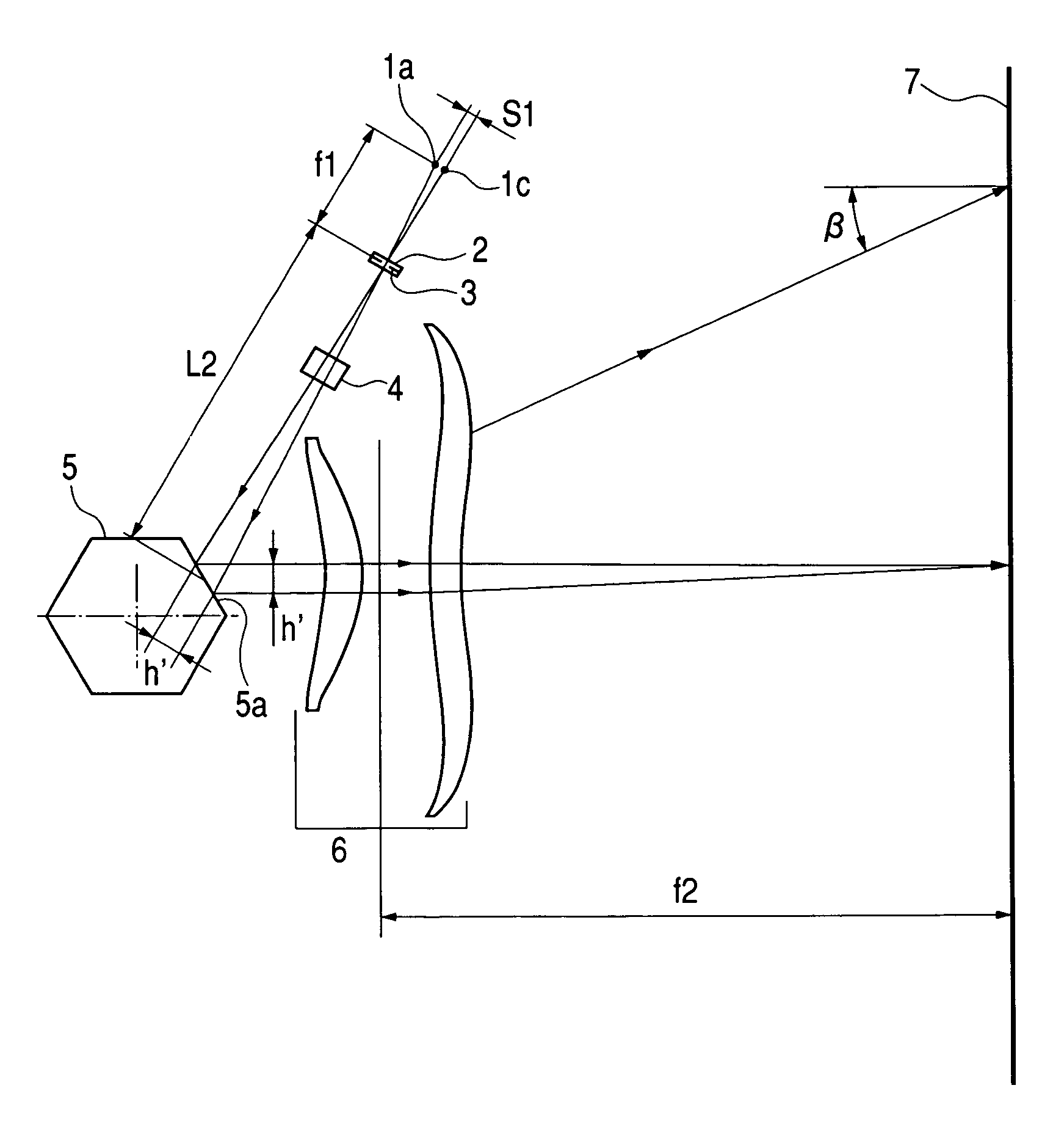
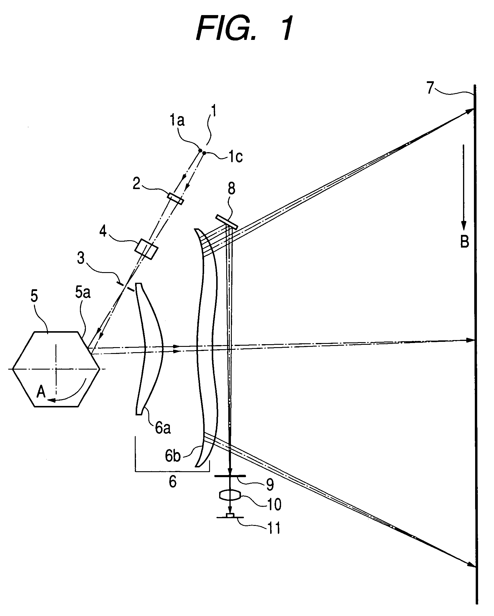
[0075]FIG. 1 is a cross-sectional view in a main-scanning direction illustrating a main portion of a multi-beam optical scanning apparatus of a first embodiment according to the present invention.

[0076]Here, the main-scanning direction means a direction perpendicular to a rotational axis of a deflecting unit and an optical axis of a scanning optical system (i.e., a direction along which a light beam is reflected (deflection-scanned) by the deflecting unit), and the sub-scanning direction means a direction parallel to the rotational axis of the deflecting unit. Further, the main-scanning section means a plane parallel to the main-scanning direction and including the optical axis of the scanning optical system. The sub-scanning section means a plane perpendicular to the main-scanning section.

[0077]In FIG. 1, reference numeral 1 represents a light source unit comprised of a plurality of light emitting or radiation portions spaced from each other in both the main...

second embodiment

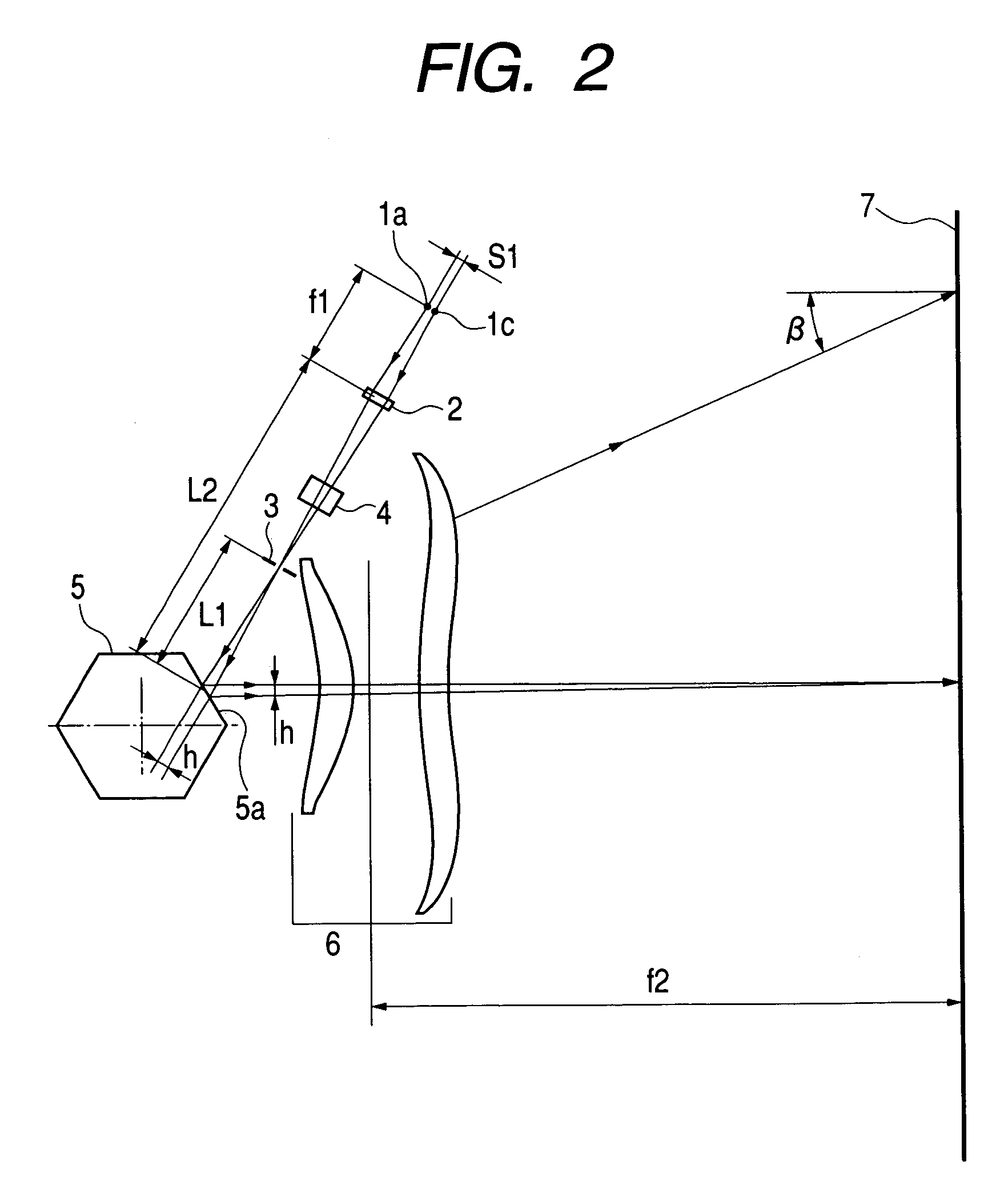
[0160](Second Embodiment)

[0161]FIG. 12 is a cross-sectional view in the main-scanning direction illustrating a multi-beam optical scanning apparatus of a second embodiment according to the present invention. In FIG. 12, like reference characters designate the same elements as those illustrated in FIG. 1.

[0162]The second embodiment is different from the first embodiment in that the displacement or variation of the image location of each of light beams emitted from light emitting portions 1a, 1b and 1c is reduced by satisfying a condition or formula (11) described later in a construction in which a light source unit 12 is comprised of the three light emitting portions 1a, 1b and 1c, and a writing start position synchronous signal detecting unit is comprised of a BD lens 13, a BD slit 14, a BD sensor 11, and the like. Other structure and optical function of the second embodiment are approximately the same as those of the first embodiment, thereby achieving the same technical advantages...

third embodiment

[0201](Third Embodiment)

[0202]FIG. 19 is a cross-sectional view in the main-scanning direction illustrating a multi-beam optical scanning apparatus of a third embodiment according to the present invention. In FIG. 19, like reference characters designate the same elements as those illustrated in FIG. 1.

[0203]The third embodiment is different from the first embodiment in that a BD slit 19 is adapted to be movable along a direction in which plural light beams incident on the BD slit 19 travel. Other structure and optical function of the third embodiment are approximately the same as those of the first embodiment, thereby obtaining similar technical advantages.

[0204]In FIG. 19, reference numeral 19 designates the BD slit, and the BD slit 19 is adapted to be movable along the direction in which plural light beams incident on the BD slit 19 travel.

[0205]In the third embodiment, since the BD image height is set outside the effective image region, a portion of the fθ lens through which the ...


PUM


Abstract

An object is to obtain a multi-beam optical scanning apparatus in which a displacement of an image location of each of light beams emitted from a plurality of light emitting portions is reduced, and which is suitably usable in a high-speed and high-image-quality application, and an image forming apparatus using the multi-beam optical scanning apparatus.A multi-beam optical scanning apparatus includes a light source unit 1 having plural light emitting portions disposed with being spaced from each other in a main-scanning direction, a first optical system 2 for changing conditions of plural divergent light beams emitted from the light source unit, a stop 3 for restricting widths of the plural light beams transmitted through the first optical system, a deflecting unit 5 for reflecting the plural light beams restricted by the stop, a second optical system 6 for forming images of the plural light beams reflected by the deflecting unit on a surface 7 to be scanned, and a detecting unit for detecting a writing start position synchronous signal for controlling a timing of a scanning start position on the surface to be scanned. The individual elements are designed so as to satisfy a predetermined condition.

Description

BACKGROUND OF THE INVENTION[0001]1. Field of the Invention[0002]The present invention relates to a multi-beam optical scanning apparatus and an image forming apparatus using the same, and particularly to a multi-beam optical scanning apparatus which is suitably usable in an image forming apparatus, such as a laser beam printer, a digital copying machine, and a multi-function printer that employ the electrophotographic process, for example, and can achieve operation with high speed and high recording density by using a light source unit having a plurality of light emitting or radiation portions.[0003]2. Related Background Art[0004]FIG. 23 is a cross-sectional view taken along a main-scanning direction and schematically illustrating a main portion of a conventional multi-beam optical scanning apparatus.[0005]In FIG. 23, plural light beams emitted, for example, from a multi-beam semiconductor laser 91 with plural light emitting portions (light emitting points) are converted into approx...

Claims


Application Information

Patent Timeline
Patent Type & Authority Patents(United States)
IPC IPC(8): B41J2/435B41J2/44B41J2/47G02B26/10G02B26/12G03G15/00H04N1/036H04N1/113
CPCB41J2/473
Inventor ISHIBE, YOSHIHIRO
Owner CANON KK
Features
  • R&D
  • Intellectual Property
  • Life Sciences
  • Materials
  • Tech Scout
  • Unparalleled Data Quality
  • Higher Quality Content
  • 60% Fewer Hallucinations
Learn More