
Signal DC offset correction method and device

a technology of offset correction and signal, applied in the direction of dc level restoring means or bias distorting correction, digital transmission, baseband system details, etc., can solve the problems of low accuracy of estimated dc and basically constant signals, and achieve the effect of cheap and reliabl

Active Publication Date: 2006-10-10
NOKIA TECHNOLOGLES OY
View PDF11 Cites 5 Cited by
  • Summary
  • Abstract
  • Description
  • Claims
  • Application Information

AI Technical Summary

Benefits of technology

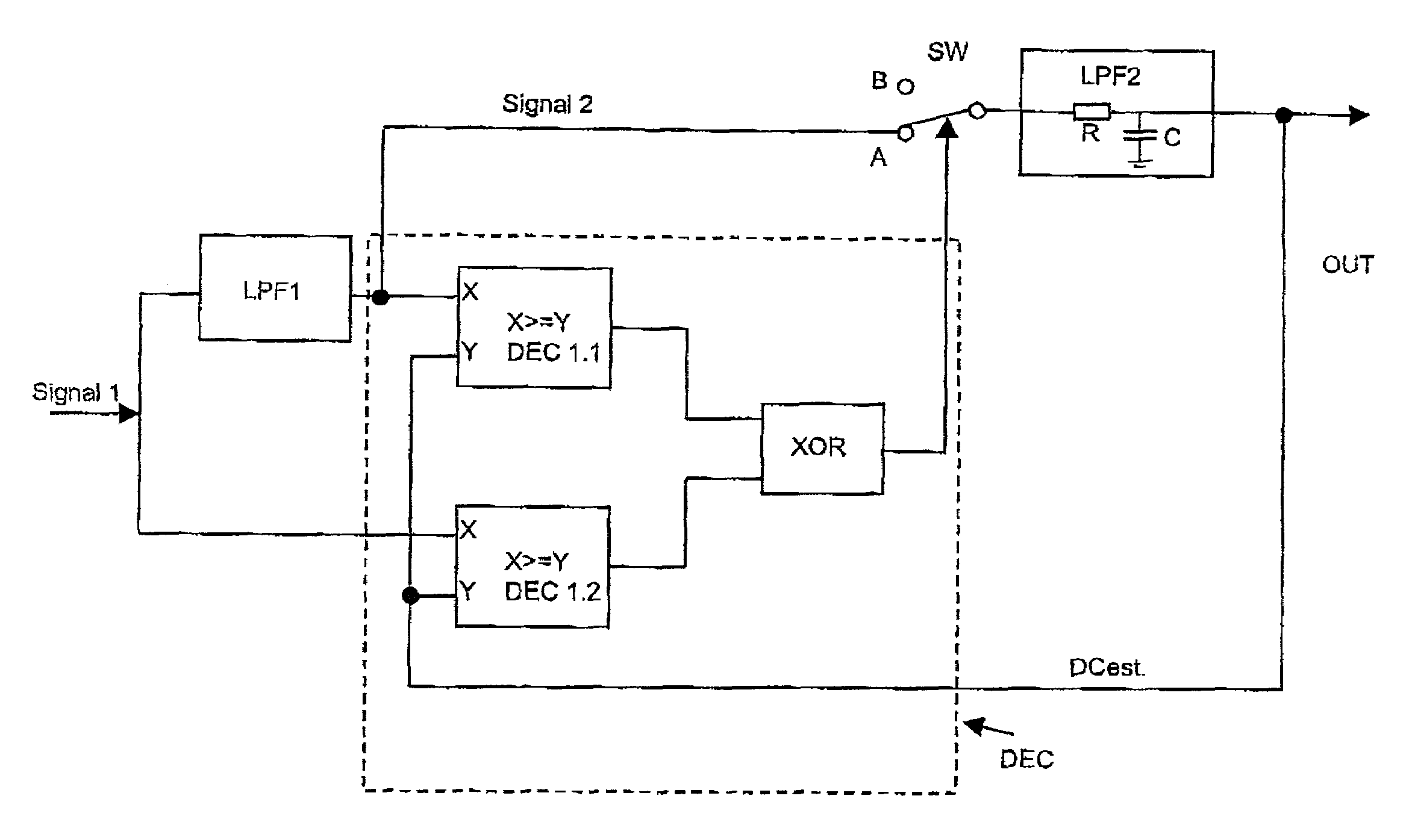
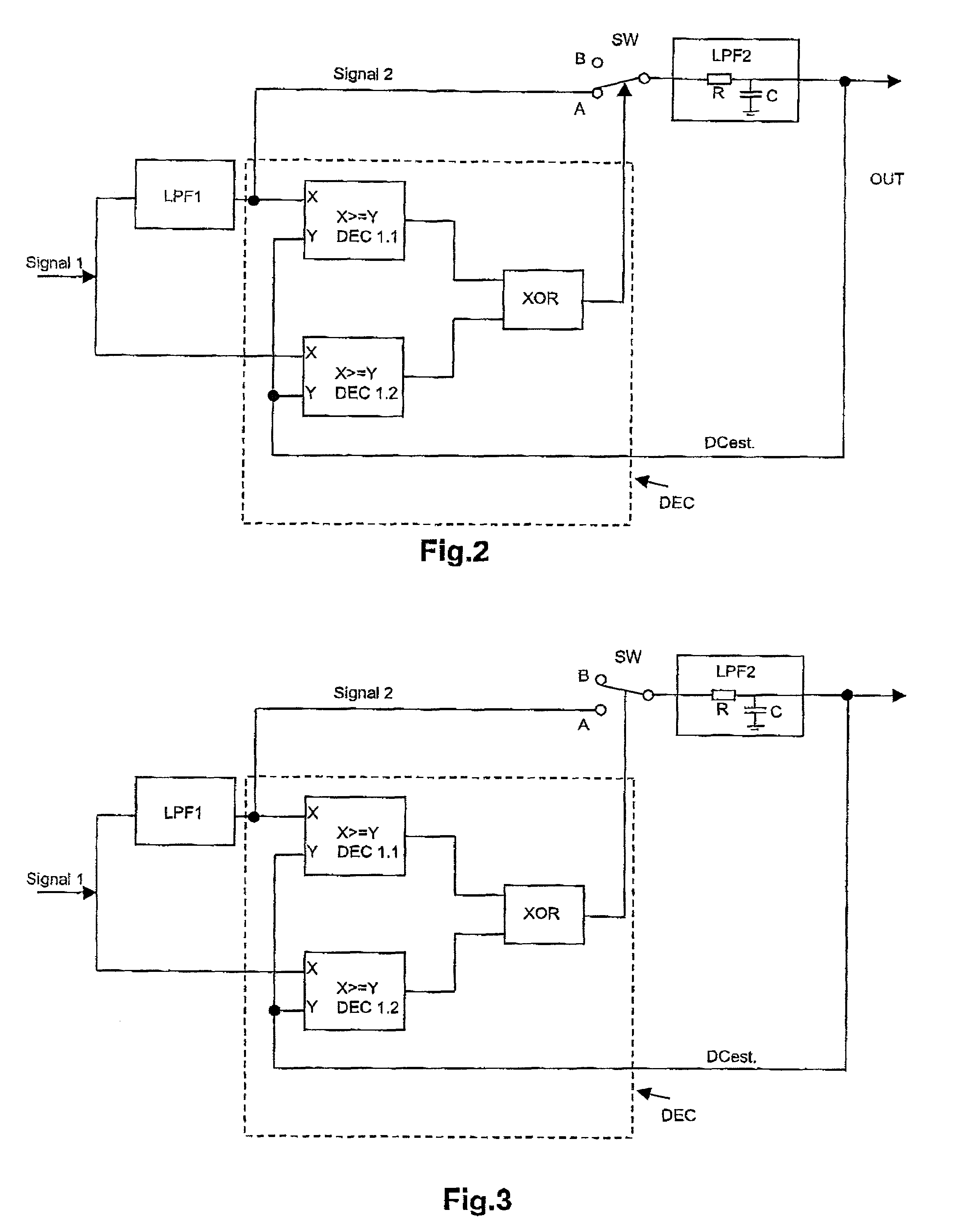
[0019]This decision circuit provides a cheap and reliable circuit for deciding when the two stages according to the present invention are reached and switches between these stages correspondingly.

Problems solved by technology

For systems having a shorter preamble, the DC estimation has to be faster which usually results in a lower accuracy of the estimated DC.
One difficulty with those DC tracking algorithms are sequences of equal bits that result in a signal that is basically constant.

Method used


Image

  • Signal DC offset correction method and device
  • Signal DC offset correction method and device
  • Signal DC offset correction method and device

Examples


Embodiment Construction

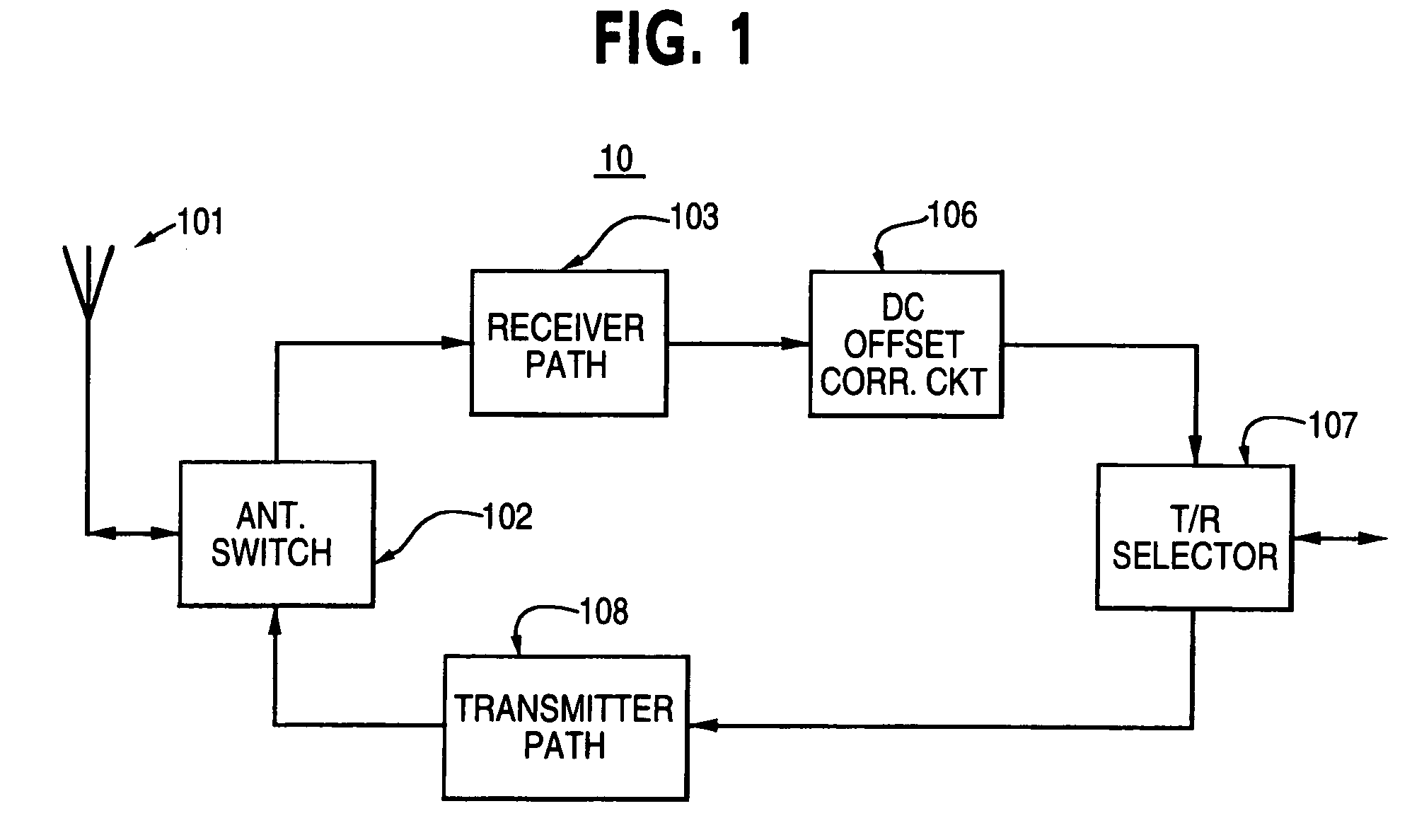
[0029]FIG. 1 shows a transceiver of a communication device 10 with a DC correction circuit 106 according to the invention. The communication device 10 might be a transceiver module working in accordance with the Bluetooth standard. The transceiver has an antenna 101 for transmitting and receiving radio frequency signals. The antenna is connected to an antenna switch 102 which alternately connects the receiver path 103 or a transmitter path 108 of the transceiver to the antenna. The antenna switch 102 might be also implemented by duplex filters.

[0030]The transmitter path is only represented by block 108 in FIG. 1 because it can be built in any way a person skilled in the art might wish to implement it without taking care for the invention as described in this document.

[0031]The receiver path 103 of the device 10 comprises, for example, low noise amplification, down conversion, filtering at different stages of the receive path, mixing and demodulation. A person skilled in the art is a...


PUM


Abstract

A method and a device for estimating the DC offset portion of a signal, especially of a signal containing parts with sinusoidal shape, for example a signal which results from demodulation of a frequency modulated receive signal. A method is presented for correcting the direct current offset portion (DC offset) of a first signal which includes phase shifting the first signal for obtaining a second signal and comparing the first signal and the second signal with an estimated DC offset. The estimated DC offset is adjusted if the result of the comparison is that the first signal and the second signal are on different sides of the estimated DC offset and the estimated DC offset remains constant as long as the result of the comparison is that the first signal and the second signal are on the same side of the estimated DC offset.

Description

BACKGROUND OF THE INVENTION[0001]The invention relates to a method and a device for estimating the DC offset portion of a signal, especially of a signal containing parts with a sinusoidal shape, for example a signal which results from demodulation of a frequency modulated receive signal. After demodulation of a frequency modulated signal, the problem of carrier frequency estimation transforms into Direct Current (DC) estimation of the received signal. For simplicity only the abbreviated term DC estimation will be used in the present specification. The term tracking is used if the DC value is continuously estimated not only during the beginning of a packet but also for the remaining portion of a packet. In particular the present invention relates to a device for correcting the DC offset of a signal, for example a received radio frequency signal after demodulation.[0002]The present invention is especially designed for systems where fast and reliable DC estimation is difficult due to t...

Claims


Application Information

Patent Timeline
Patent Type & Authority Patents(United States)
IPC IPC(8): H04L25/06H03L5/00H04B1/69H04L27/14
CPCH04L25/062H04L25/063H04L27/142
Inventor SCHETELIG, MARKUSBURGESS, PAUL
Owner NOKIA TECHNOLOGLES OY
Learn More