Building panels

US7121058B2Inactive Publication Date: 2006-10-17UNILIN NORDIC AB

Image

  • Building panels
  • Building panels
  • Building panels

Examples


Embodiment Construction

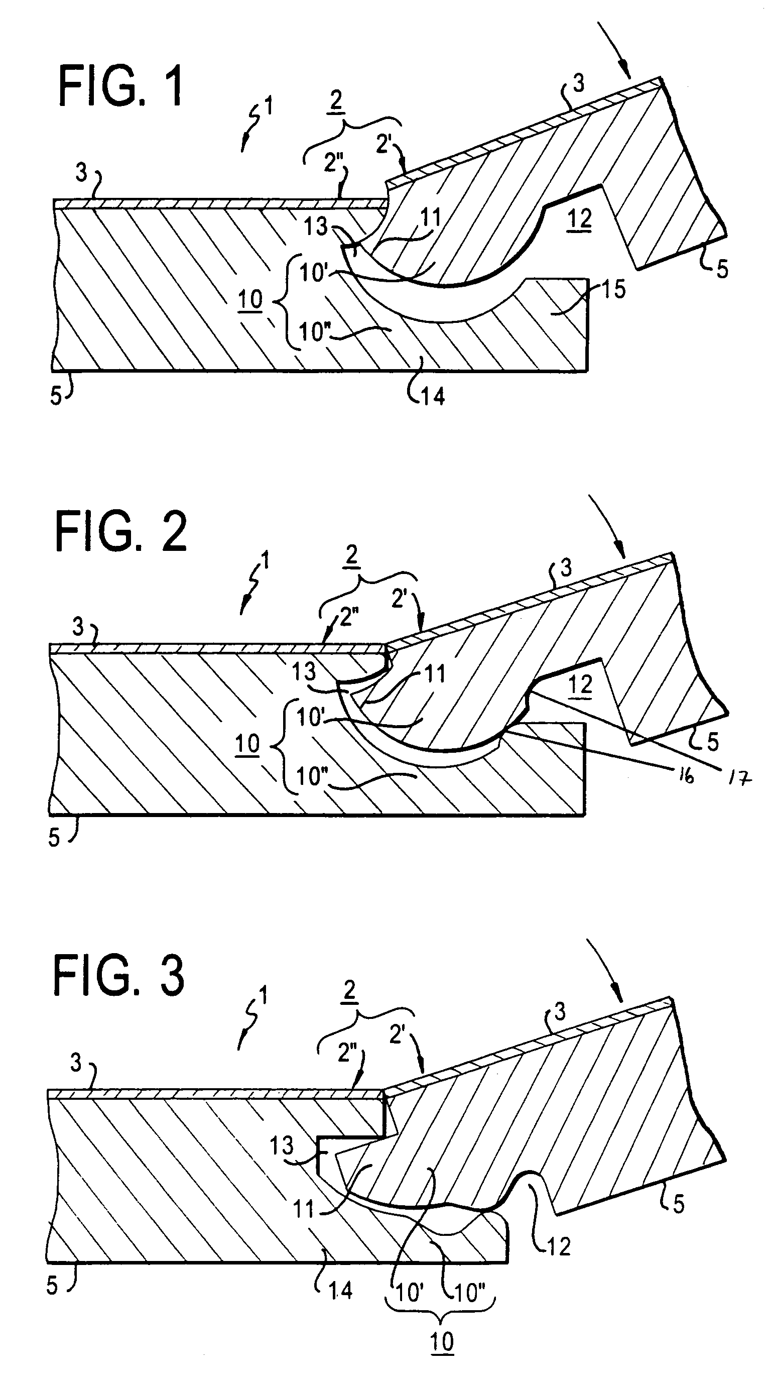
[0037]FIG. 1 shows, in cross-section, a first and a second edge 2I and 2II respectively, during assembly. The figure shows parts of a flooring material comprising sheet-shaped floor elements 1 with a mainly square or rectangular shape. The floor elements 1 are provided with edges 2, a lower side 5 and an upper decorative layer 3. The floor elements 1 are intended to be joined by means of joining members 10. Such floors floor elements, for example, be constituted of solid wood, fibre board, such as medium density fibre board (MDF), particle board, chip board, or any other construction comprising pieces or particles of wood, including combinations of plastic elements and the particles or pieces of wood. The floor elements 1 are provided with male joining members 101 on a first edge 2I while a second edge 2II of the floor elements 1 are provided with a female joining member 10II. The second edge 2II is arranged on a side opposite to the first edge 2I. The male joining member 10I is pro...


PUM

PropertyMeasurementUnit
Thicknessaaaaaaaaaa
Thicknessaaaaaaaaaa
Force constantaaaaaaaaaa

Abstract

Flooring material comprising sheet-shaped floor elements with a mainly square or rectangular shape. The floor elements are provided with edges, a lower side and an upper decorative layer. The floor elements are intended to be joined by means of joining members. The floor elements are provided with male joining members on a first edge while a second edge of the floor elements are provided with a female joining member. The male joining member is provided with a tongue and a lower side groove while the female joining member is provided with a groove and a cheek, the cheek being provided with a lip. The floor elements are provided with a male vertical assembly joining member on a third edge while a fourth, opposite, edge is provided with female vertical assembly joining member. The floor elements are alternatively provided with a male vertical assembly joining member on a third edge while a fourth, opposite, edge also is provided with male vertical assembly joining member. Adjacent male vertical assembly joining members are hereby joined by means of a separate vertical assembly joining profile. Two adjacent edges of a floor element can hereby, at the same time, and in the same turning motion, be joined with a floor element adjacent to the first edge and a floor element adjacent to the third or fourth edge.

Description

CROSS-REFERENCE TO RELATED APPLICATIONS[0001]This application is a Continuation-In-Part of U.S. application Ser. No. 09 / 672,076, filed Sep. 29, 2000, now U.S. Pat. No. 6,591,568, and a Continuation-In-Part of U.S. application Ser. No. 09 / 988,014, filed Nov. 16, 2001, now abandoned, and a Continuation-In-Part of U.S. application Ser. No. 10 / 242,674, filed Sep. 13, 2002, and additionally claims priority from Swedish Application No. 0001149-4, filed Mar. 31, 2000, the entire disclosures of which are incorporated herein by reference in their entirety.BACKGROUND[0002]1. Field of the Invention[0003]The present invention relates to a flooring material comprising sheet-shaped floor elements which are joined by means of joining members.[0004]2. Background[0005]Prefabricated floor boards provided with tongue and groove at the edges are quite common nowadays. These can be installed by the average handy man as they are very easy to install. Such floors can, for example, be constituted of solid ...

Claims


Application Information

Patent Timeline
17 Oct 2006
Publication
US7121058B2
IPC
E04B2/08; B29C65/00; E04F15/04; B32B7/04; E04B2/00; E04F13/00; E04F15/02
CPC
E04F15/02; E04F15/02038; E04F15/04; E04F2201/0115; E04F2201/0138; E04F2201/0153; E04F2201/026; E04F2201/05
Inventors
PALSSON, JORGEN; SJOBERG, AKE