
Device and method for applying patterns and/or labels to a substantially flat surface of an article

a technology of pattern and/or label, applied in the direction of embossing decorations, stencilling apparatus, decorative arts, etc., can solve the problems of erasure marks visible on the surface, inconvenient application, and many users' problems when using single-layer stencils as well as multi-layer stencils

Inactive Publication Date: 2006-10-17
MELLIS HORST
View PDF18 Cites 7 Cited by
  • Summary
  • Abstract
  • Description
  • Claims
  • Application Information

AI Technical Summary

Benefits of technology

[0014]It is an object of the present invention to provide a device and a method for applying patterns and / or labels onto a substantially flat surface of an article, in particular, a postcard or greeting card, a leaf insert for photo albums, a certificate or the like, by using stencils which device and method enable, not only for multi-layer stencils, an exact alignment of each stencil, by which a pattern and / or label is to be transferred onto a surface, relative to the surface onto which the pattern or the label is to be transferred, but also relieve the user, as needed, practically of any free choice with regard to the alignment of the pattern relative to the surface.

Problems solved by technology

It was found that many users have problems when using the single-layer as well as the multi-layer stencils.
An obvious problem in the case of multi-layer stencils that must be employed sequentially is the required alignment of a stencil that is applied at a later time relative to the pattern that has been created by using the first stencil.
This method is however imprecise because it allows only an approximate alignment that is purely based on visual estimation of the second and any additional stencil relative to the pencil markings.
Moreover, when removing the pencil markings, there are usually erasure marks visible on the surface, in particular, because the paper or cardboard that is to be processed is sensitive with regard to mechanical wear and can be easily damaged upon using an eraser for removing the markings.
In the case of single-layer stencils, the alignment of the stencil relative to the card is a problem for many users because the number of design possibilities as a result of free choice regarding the positioning of the stencil relative to a card is perceived by many users as a disadvantage rather than an advantage.
This problem also occurs in regard to multi-layer stencils because the first stencil can be freely positioned relative to the card.
However, this does not relieve the user from the free choice with regard to the arrangement of the pattern relative to a card; a limitation is provided only in the case where punched cards are used that can be fixed on the frame.
The device therefore is not suitable for producing high-quality greeting cards that are to be free of punched holes.
In this arrangement, there is also the problem of free choice because the individual stencils can be positioned in a longitudinal direction of the web at any location.

Method used


Image

  • Device and method for applying patterns and/or labels to a substantially flat surface of an article
  • Device and method for applying patterns and/or labels to a substantially flat surface of an article
  • Device and method for applying patterns and/or labels to a substantially flat surface of an article

Examples


Embodiment Construction

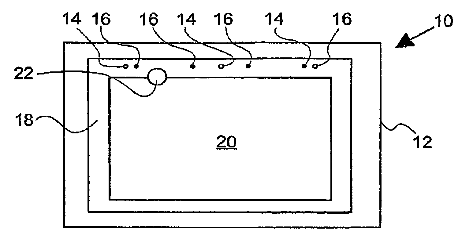
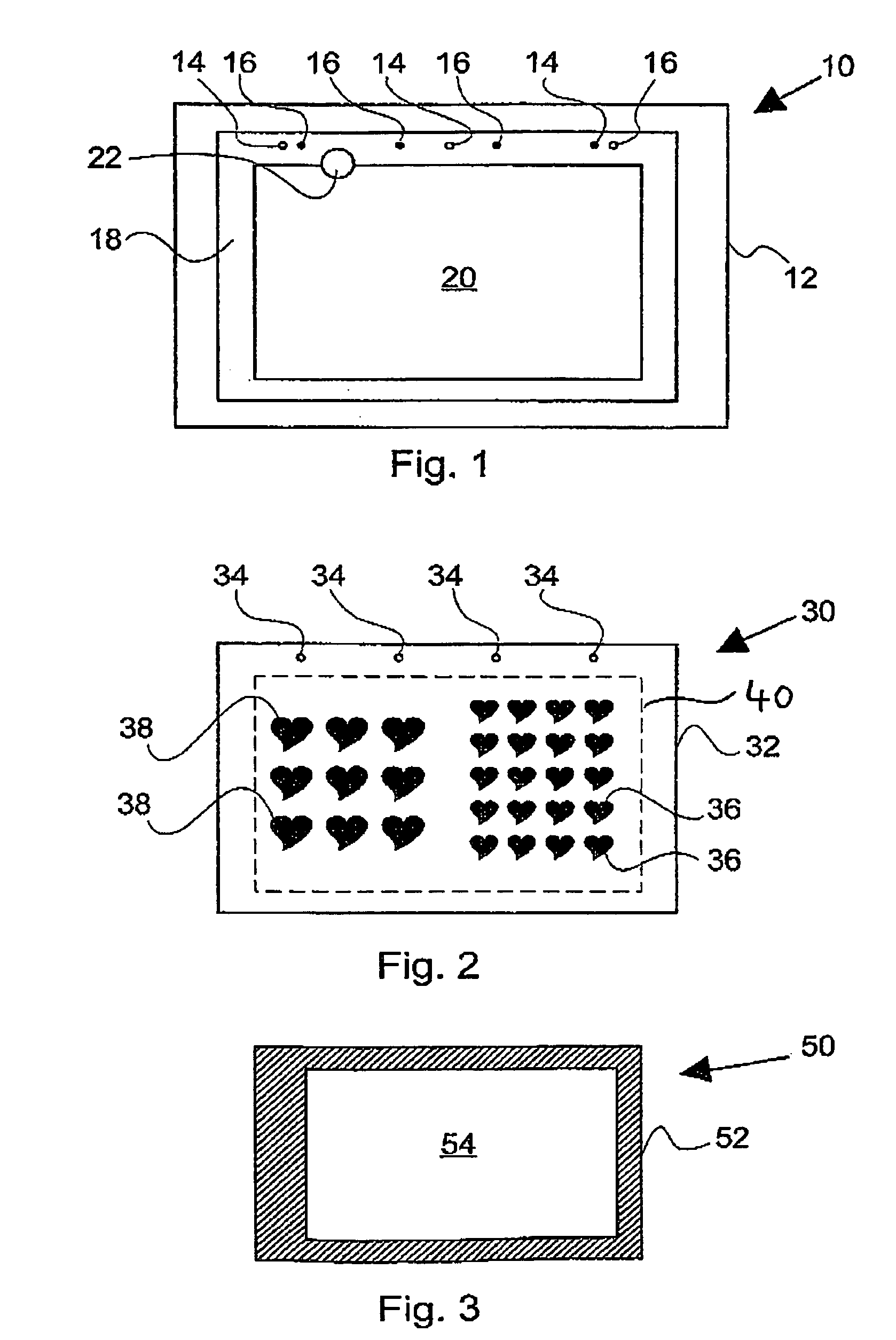
[0028]The stencil holder 10 shown in FIG. 1 is designed for holding a stencil, for example, a stencil as the one shown in FIG. 2, and for receiving an article having a surface to be processed. The article with the surface to be processed will generally be a card.

[0029]The stencil holder 10 comprises in this embodiment a base member in the form of a base plate or work plate 12 in which in this embodiment seven receiving openings 14 are provided. FIG. 1 shows only three receiving openings that are identified by reference numerals because the other four receiving openings have inserted therein short securing pins 16 so that these four receiving openings in the plan view illustrated in FIG. 1 appear filled.

[0030]The securing pins 16 can be, for example, short sections of a cylindrical rod or double cone-shaped shelf supports as they are known in the furniture industry. These purely exemplary shapes of securing pins have each a round cross-section so that the receiving openings 14 also h...


PUM


Abstract

A device creating patterns on greeting cards and the like has at least one stencil for applying a pattern onto a flat surface. A stencil holder that has securing elements for securing the at least one stencil in a predetermined position relative to the stencil holder is provided. The stencil holder also has elements for positively securing the surface of the article onto which the pattern is to be applied relative to the stencil holder. The elements for securing the surface of the article are in the form of a recess that provides a positive securing action for the surface of the article alone or in combination with an adapter.

Description

CROSS REFERENCE TO RELATED APPLICATIONS[0001]This application is a continuation of International Application PCT / DE03 / 00204 with an international filing date of Jan. 27, 2003, not published in the English language under PCT Article 21(2), and now abandoned.BACKGROUND OF INVENTION[0002]1. Field of the Invention[0003]The invention relates to a device and a method for applying patterns and / or labels to a substantially flat surface of an article, in particular, a postcard or greeting card, a leaf insert for photo albums, a certificate or the like, by employing a stencil.[0004]2. Description of the Related Art[0005]The terms postcard or greeting card are meant to include all conceivable types of greeting cards, invitation cards, message cards, congratulatory notes and the like. However, since devices and methods of the aforementioned kind are usually employed for producing hand-crafted greeting cards, often only the term card will be used in the following without this limiting the device...

Claims


Application Information

Patent Timeline
Patent Type & Authority Patents(United States)
IPC IPC(8): B31F1/07B05C17/08B41F15/34B43L13/00B43L13/20B44B11/02B44C1/24
CPCB43L13/00B43L13/201B44C1/24
Inventor MELLIS, HORST
Owner MELLIS HORST
Learn More