Method for Controlling an Electronically Commutated Polyphase DC Motor

a technology of electronic commutation and polyphase dc motor, which is applied in the direction of electronic commutator, motor/generator/converter stopper, dynamo-electric converter control, etc., can solve the problems that other commutation forms than this sinusoidal commutation cannot be implemented with this known method, and increase costs, etc., to achieve the effect of little complexity

Inactive Publication Date: 2014-10-09
CONTINENTAL TEVES AG & CO OHG
View PDF6 Cites 6 Cited by
  • Summary
  • Abstract
  • Description
  • Claims
  • Application Information

AI Technical Summary

Benefits of technology

[0029]With such a logic circuit according to the invention, different drive concepts with any desired selectable commutation form can be realized with little complexity using hardware, in particular without additional processor computation power.

Problems solved by technology

A microprocessor has the advantage of the greatest possible flexibility, but has increased computation capacity which it needs to have available, which also results in increased costs.
Commutation forms other than this sinusoidal commutation cannot be implemented with this known method.

Method used


Image

  • Method for Controlling an Electronically Commutated Polyphase DC Motor
  • Method for Controlling an Electronically Commutated Polyphase DC Motor
  • Method for Controlling an Electronically Commutated Polyphase DC Motor

Examples


Embodiment Construction

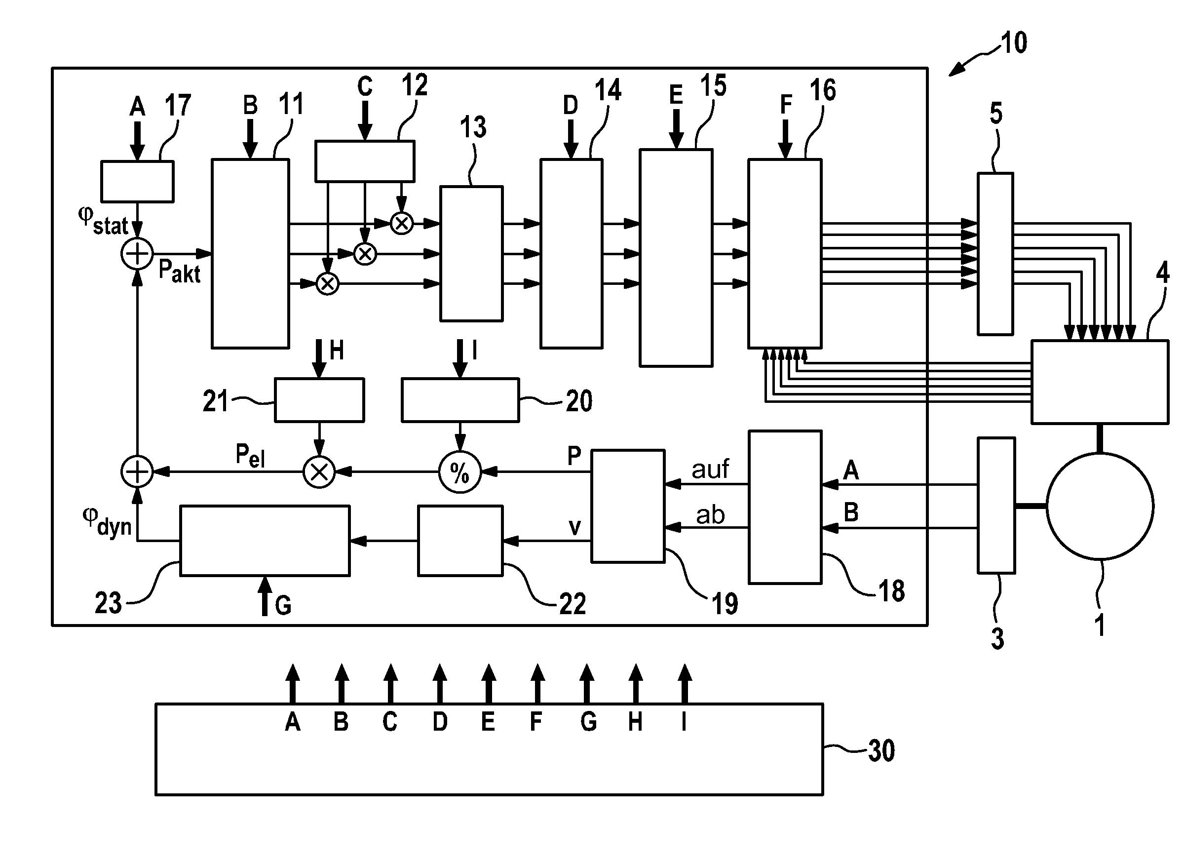
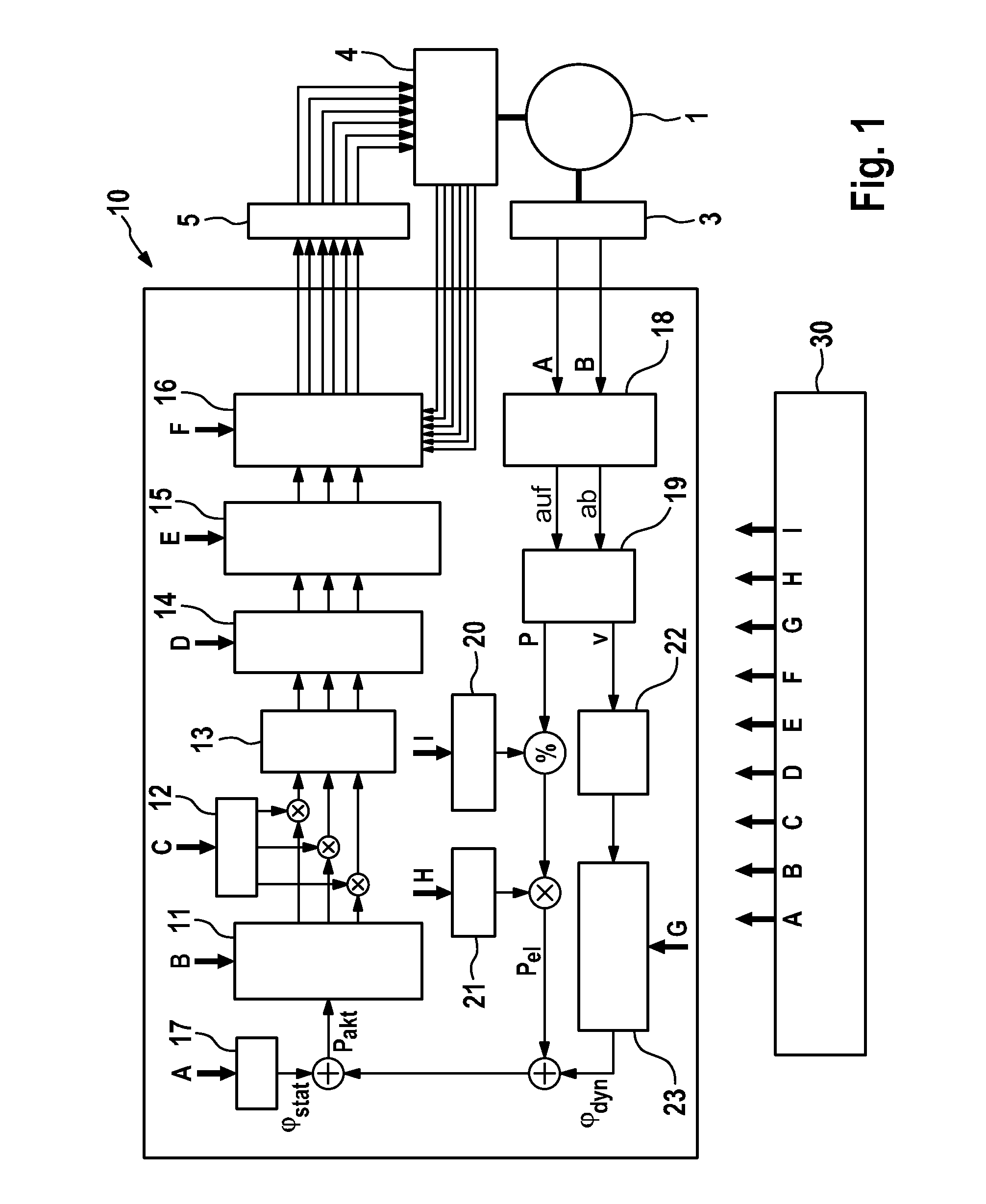
[0035]As shown in FIG. 1, a brushless DC motor (BLDC motor) 1 is driven by a power output stage 4, which is driven via a half-bridge driver circuit 5 by a logic circuit 10. This logic circuit 10 includes a plurality of function blocks 11 to 23, of which some are configured by a control unit 30 for starting up the BLDC motor 1.

[0036]In addition, the BLDC motor 1 has a quadrature sensor as angle sensor 3, which is generally in the form of a Hall sensor system or a MR (magnetic resonance) angle sensor system for detecting the position of the rotor of the BLDC motor 1. This quadrature sensor 3 is in the form of an incremental transducer and generates an A signal and a B signal, which are supplied to the logic circuit 10.

[0037]On startup of the BLDC motor 1, configuration data A to I are generated, as depicted in FIG. 1, by the control unit 30, and these configuration data are supplied to some of the function blocks 11 to 23 for configuration of the logic circuit 10, as will be set forth...


PUM


Abstract

A method for controlling a brushless DC motor (BLDC motor) having a rotor, a stator and an angle sensor and a logic circuit for generating the phase voltages of the windings depending on the phase angle of the rotor. The logic circuit access a lookup table, in which to implement commutation with block-shaped, trapezoidal, sinusoidal, sinoid-based signal waveforms. The drive values are stored for the electrical phase angle of the rotor for generating phase voltages (VU, VV, VW) for the windings. A control unit generates configuration data for the logic circuit determine the commutation form, and depending on the form, the drive values are supplied to a PWM generator for generating control signals (VU, VV, VW) depending on the electrical phase angle of the rotor angle, which PWM control signals can be used to control the phase currents in the windings.

Description

CROSS REFERENCE TO RELATED APPLICATIONS[0001]This application claims priority to German Patent Application No. 10 2011 080 941.4, filed Aug. 15, 2011; and PCT / EP2012 / 065007, filed Aug. 1, 2012.FIELD OF THE INVENTION[0002]The invention relates to a method for controlling an electronically commutated polyphase DC motor (also called a brushless DC or BLDC motor) with a pole number≧2 and with a winding system with a plurality of winding phases, in particular three winding phases, having a rotor, a stator and a quadrature sensor detecting the angle of the rotor. In addition, the invention relates to an apparatus for implementing the method according to the invention.BACKGROUND[0003]Electronically commutated DC motors (BLDC motors) are generally known and have a rotor, for example implemented as a permanent magnet, which is driven by an excitation field moving in rotary fashion. This excitation field is produced by a, for example, three-phase winding system by virtue of the winding phases...

Claims


Application Information

Patent Timeline
Patent Type & Authority Applications(United States)
IPC IPC(8): H02P6/16
CPCH02P6/085H02P6/16H02P6/145H02P6/153
Inventor HEISE, ANDREASHARTMANN, RALFMICHEL, FRANKBITSCH, CHRISTIANSTAUDER, PETERKAUFMANN, TOMPACHUR, ANDREASWARMBIER-LEIDIG, BURKHARD
Owner CONTINENTAL TEVES AG & CO OHG
Why Eureka
Try Eureka