Suction frame

a suction frame and frame technology, applied in the field of suction frames, can solve the problems of affecting the operation of the suction frame,

Active Publication Date: 2018-08-09
WISCO LASERTECHN
View PDF2 Cites 5 Cited by
  • Summary
  • Abstract
  • Description
  • Claims
  • Application Information

AI Technical Summary

Benefits of technology

[0049]The present invention permits the provision of fully automatic suction frames and the retooling of the latter without any manual intervention or complicated line routing.

Problems solved by technology

It is disadvantageous herein that at all times complex line systems that are prone to defects are to be routed in the region of the suction elements, in particular of the suction bellows, on account of which a change at short notice in the configuration or the position, respectively, of the suction elements is impeded.
The lack of flexibility and the large space requirement, in the case of a multiplicity of configurations having to be catered to, are disadvantageous in these embodiments.

Method used


Image

  • Suction frame
  • Suction frame
  • Suction frame

Examples


Embodiment Construction

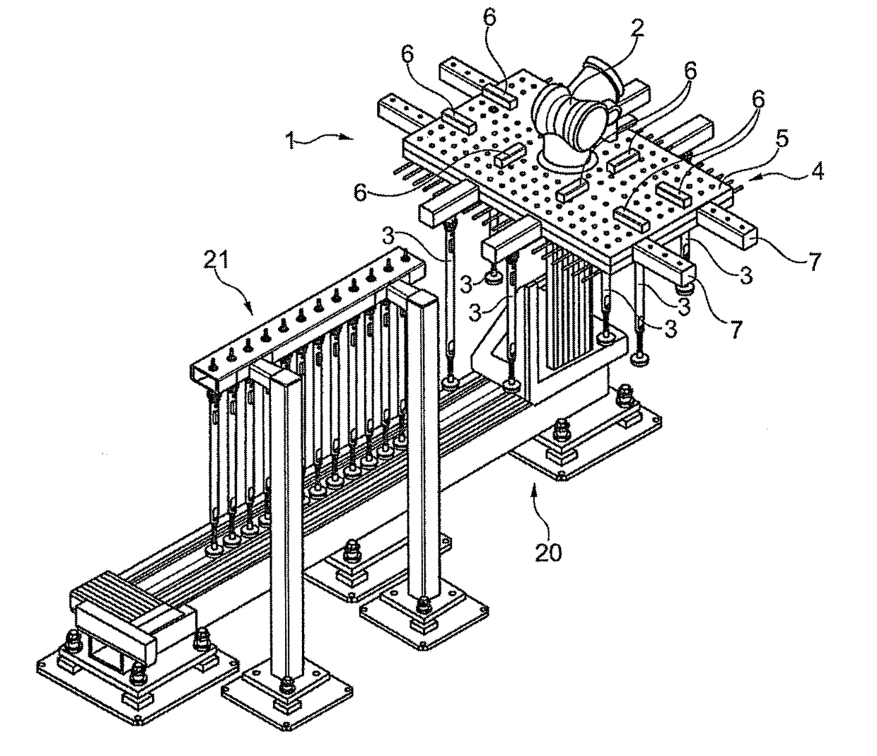
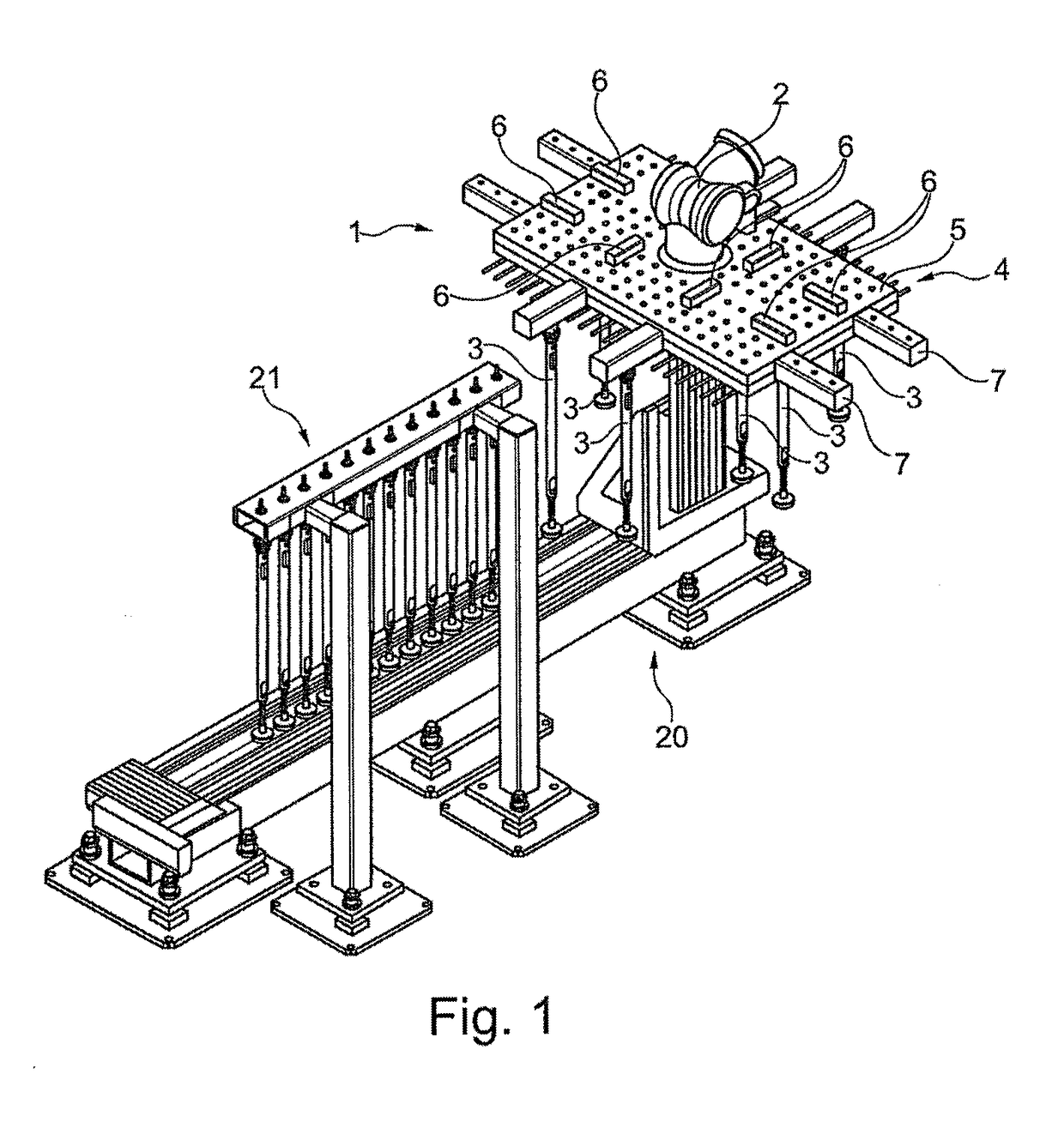
[0058]In detail, FIG. 1 shows a suction frame 1 on a robotic arm 2 (illustrated in part). Suction sticks 3 are illustrated on the suction frame 1, the suction sticks 3 having been disposed by way of a transfer station 20 from a linear accumulator 21. The transfer station illustrated will be explained in more detail in FIG. 8.

[0059]The suction frame 1 comprises an adapter 4 which is visible in the form of an upper plate 5. Vacuum couplings 6 which are contacted from the lower side by the coupling heads of the suction sticks 3 are located on the upper plate 5. For reasons of clarity, there is no line network illustrated on the upper side.

[0060]A plug-in raster which can optionally be provided with respective vacuum couplings in order for equipping that is as flexible as possible to be allowed is illustrated on the upper side of the plate 5.

[0061]The suction frame 1 furthermore comprises outriggers 7 which enable additional flexibility when equipping.

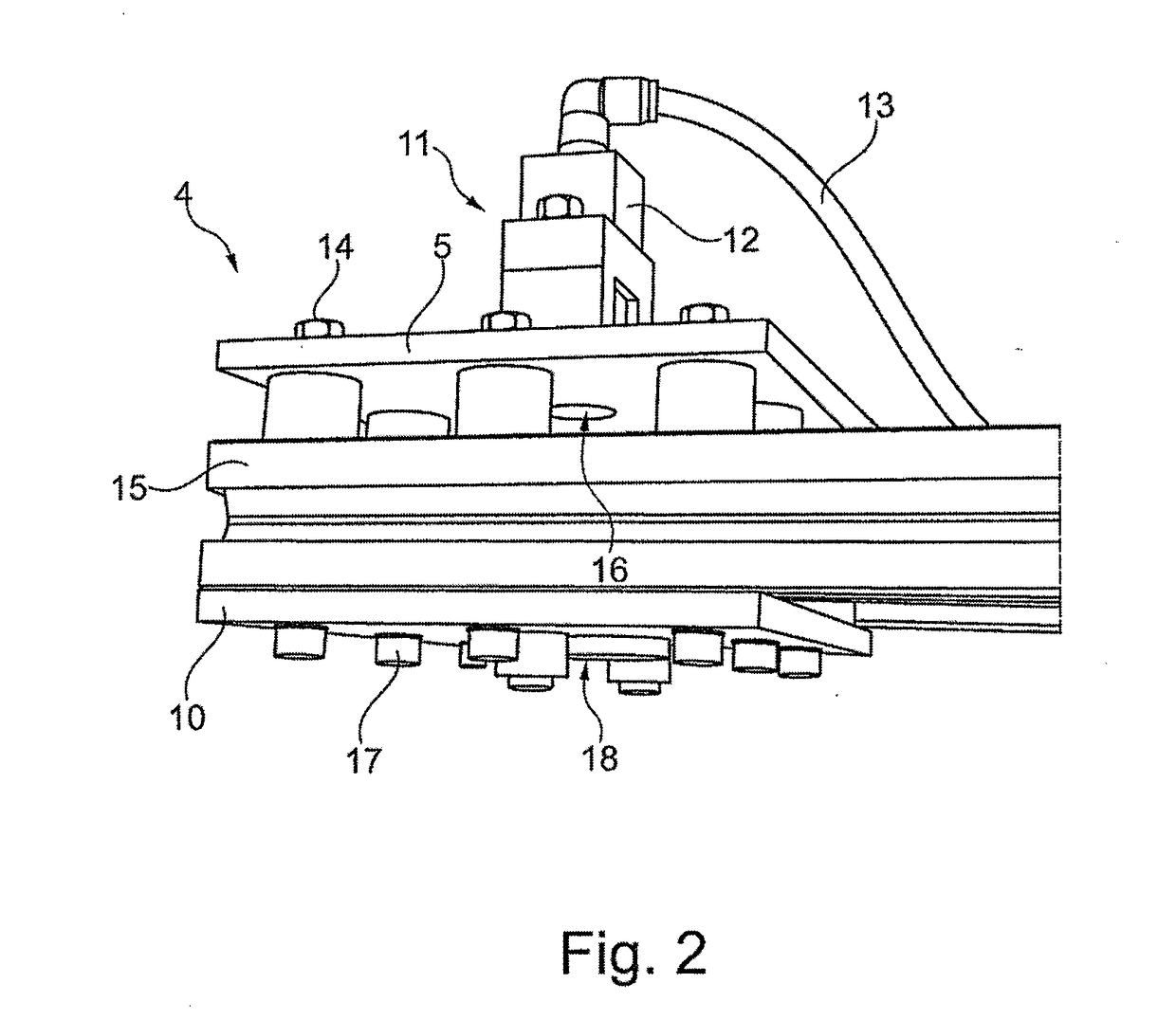
[0062]FIG. 2 in fragments shows a s...


PUM


Abstract

The present invention relates to a suction frame for conveying flat workpieces (e.g. circuit boards), a manipulator for equipping the suction frame, and a system for handling flat workpieces, e.g. circuit boards. A method for adjusting a suction frame is also claimed. Overall, the present invention allows suction frames to be equipped in a fully automatic, freely programmable manner for the production of different components within a production line.

Description

CROSS REFERENCE TO RELATED APPLICATIONS[0001]This application is a continuation of International Application No. PCT / EP2016 / 073072 filed Sep. 28, 2016, which designated the United States, and claims the benefit under 35 USC § 119(a)-(d) of German Application No. 10 2015 117 315.8 filed Oct. 12, 2015, the entireties of which are incorporated herein by reference.FIELD OF THE INVENTION[0002]The present invention relates to a suction frame, a transfer station for suction units, and a method for handling circuit boards.BACKGROUND OF THE INVENTION[0003]Suction frames in which suction elements, in particular suction sticks, are received on an adapter plate, which in turn can be fastened to an industrial robot, are known from the prior art. The suction elements herein are manually assembled at a predefined position on a raster and are, in each case by way of a hose, connected to a pump or to a suction device of another type. It is disadvantageous herein that at all times complex line system...

Claims


Application Information

Patent Timeline
Patent Type & Authority Applications(United States)
IPC IPC(8): B25J15/06B25J15/00B25J15/04B25B11/00
CPCB25J15/0616B25J15/0052B25J15/0491B25B11/005B25J15/04
Inventor ALBER, GERHARD
Owner WISCO LASERTECHN
Why Eureka
Try Eureka