
Garage light luminaire with circular compact fluorescent emergency lighting optics

a compact fluorescent and light source technology, applied in the field of electrical auxiliary lighting systems for high intensity discharge lamps, can solve the problems of short life of quartz lamps that are typically used as auxiliary lamps, inefficient conversion of electric power into lumens, and inability to provide illumination efficiently and reliably

Inactive Publication Date: 2006-10-17
GENLYTE THOMAS GRP LLC
View PDF23 Cites 37 Cited by
  • Summary
  • Abstract
  • Description
  • Claims
  • Application Information

AI Technical Summary

Benefits of technology

"The present invention provides a luminaire with a main lamp and an auxiliary lamp that can efficiently and reliably provide illumination when the main lamp fails to provide adequate illumination. The auxiliary lamp provides uniform illumination without asymmetries to the area below. Both the main lamp and the auxiliary lamp cause no shadowing. The luminaire is aesthetically appealing and meets the objective of providing a reliable and efficient solution for illuminating a wide area."

Problems solved by technology

Momentary power interruptions, such as a lightning strike or someone inadvertently hitting the on / off switch, will cause the HID lamp to extinguish.
With the power restored, restarting a hot HID lamp can take several minutes.
However, there are inherent problems with these current practices of providing auxiliary light to garage lighting systems.
The quartz lamps that are typically used as auxiliary lamps are short lived and are very inefficient in converting electric power into lumens.
This causes problems with continued reliability, maintenance, and the ability to meet auxiliary lighting needs.
A significant problem associated with these current practices is that the quartz lamps are not located at the photometric center of the fixture.
This causes the pattern of light projected from the auxiliary lamp to lack uniformity and thus portions of the lighted area are only dimly lit.
It has also been found that emergency incandescent lamp sources are inherently glary and consistently mounted off of the centerline of the fixture, causing the luminaire to be aesthetically unappealing.

Method used


Image

  • Garage light luminaire with circular compact fluorescent emergency lighting optics
  • Garage light luminaire with circular compact fluorescent emergency lighting optics
  • Garage light luminaire with circular compact fluorescent emergency lighting optics

Examples


Embodiment Construction

[0026]The present invention may best be understood by reference to the following description taken in conjunction with the accompanying figures. The figures illustrate specific embodiments in which the invention may be practiced and it is to be understood that other embodiments may be utilized as structural changes may be made without departing from the scope of the present invention.

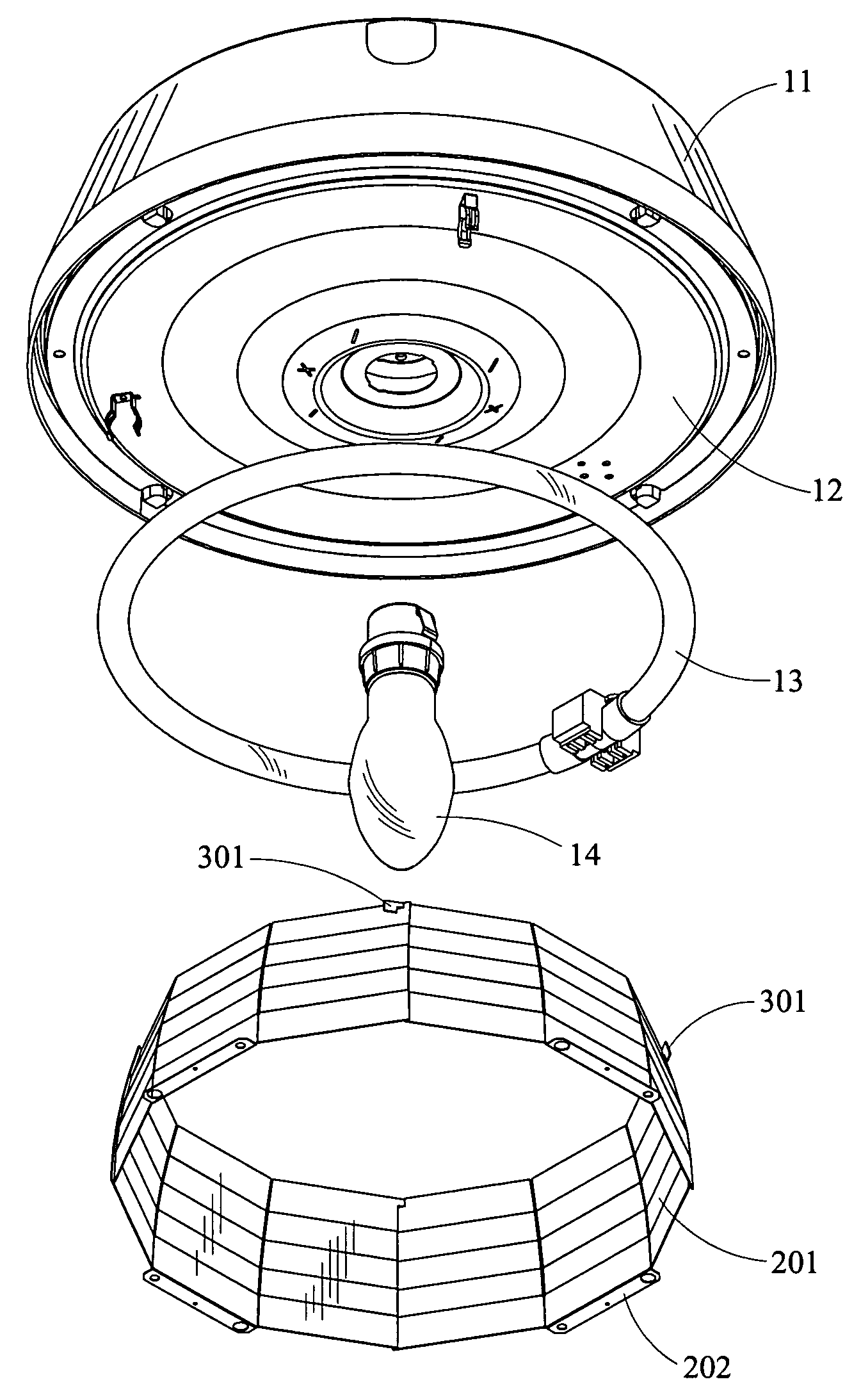
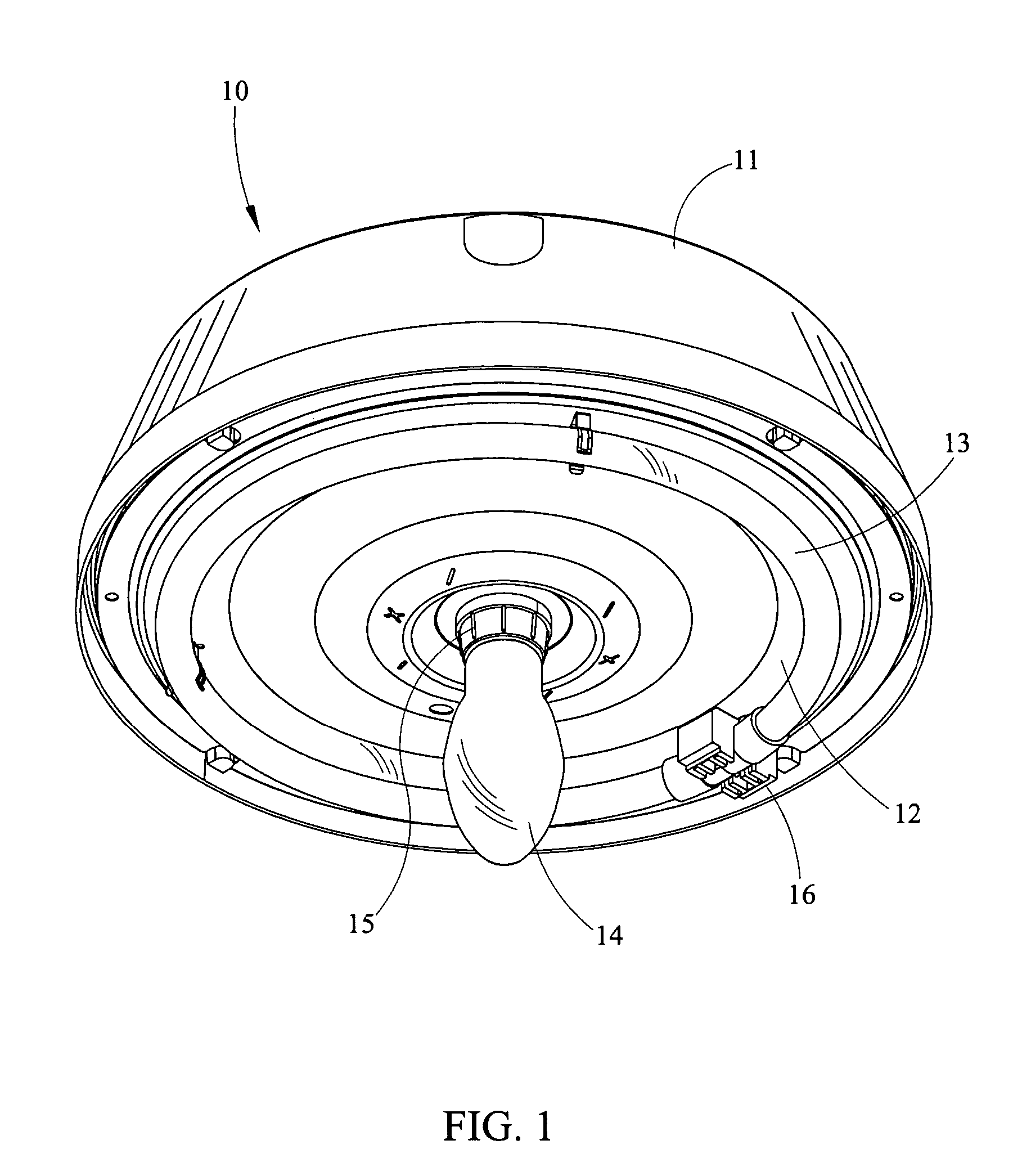
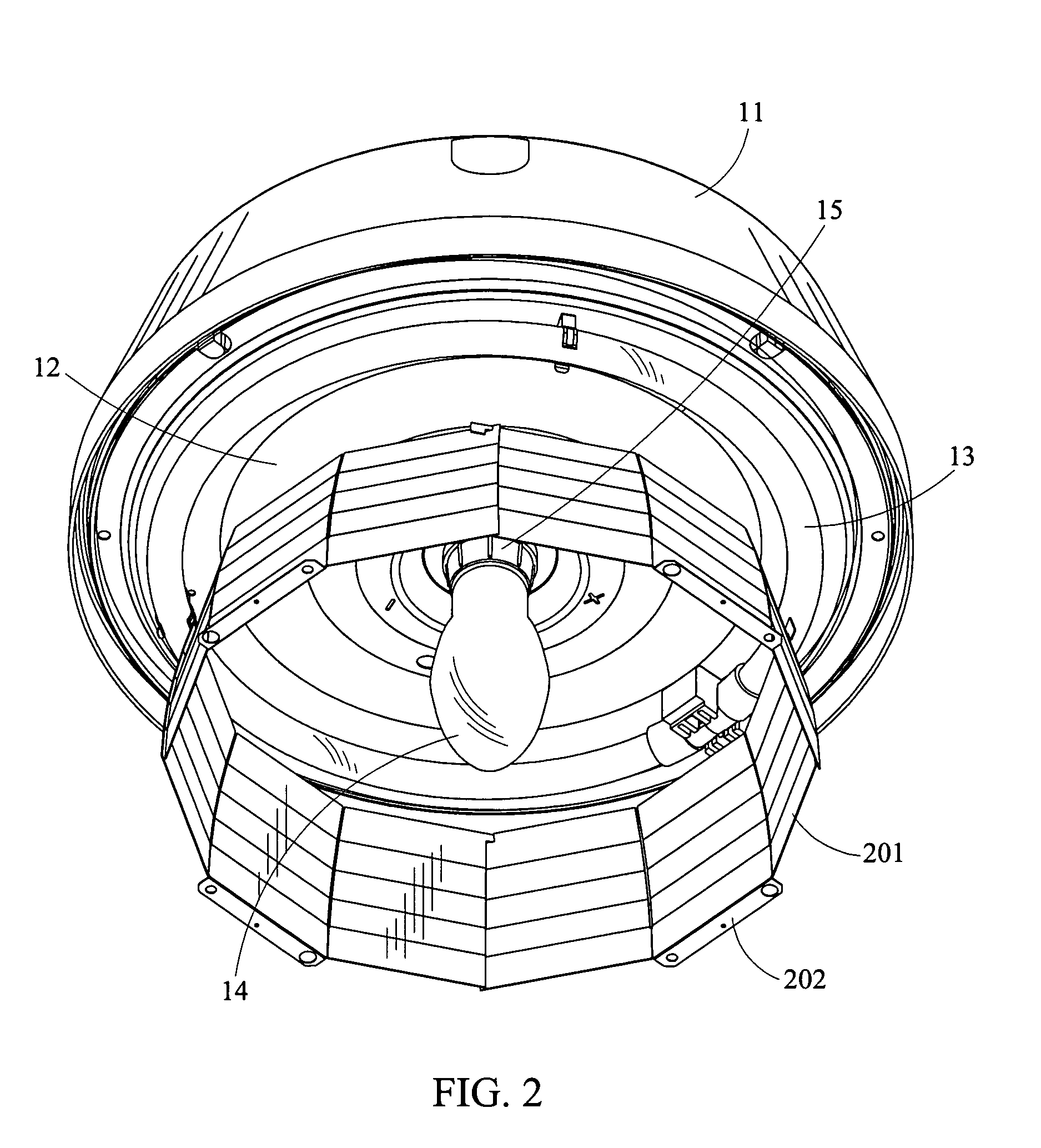
[0027]FIG. 1 is a perspective view of the garage luminaire 10 of the present invention showing the high output compact fluorescent circular auxiliary lamp 13, main HID lamp 14, housing 11, lamp mounting surface 12, and their placement within luminaire 10. In this embodiment of luminaire 10 the housing 11 is round or circular in shape. It is to be understood that housing 11 may be round, square, rectangular, oval or even irregular in shape and be within the scope of the present invention.

[0028]The housing 11 may hold the wiring, ballasts, auxiliary light switch, battery, and any other electrical equipmen...


PUM


Abstract

The present invention relates to a garage light assembly having a housing with a lamp mounting surface wherein a main high intensity discharge lamp and an auxiliary circular high output fluorescent lamp are mounted. The auxiliary lamp is mounted centrally within the assembly and above the light emitting portion of the high intensity discharge lamp so that the light pattern emitted from the auxiliary lamp is symmetrical and the auxiliary lamp does not shadow the light emitted from the high intensity discharge lamp.

Description

CROSS-REFERENCE TO RELATED APPLICATIONS[0001]Not applicable.STATEMENT REGARDING FEDERALLY SPONSORED RESEARCH OR DEVELOPMENT[0002]Not applicable.BACKGROUND OF THE INVENTION[0003]1. Field of the Invention[0004]This invention relates to the lighting arts, and in particular to an electronic auxiliary lighting system for a high intensity discharge lamp. More particularly, the auxiliary lighting system of the present invention uses as a light source a high output compact fluorescent lamp.[0005]2. Description of Related Art[0006]A high-intensity discharge (HID) lamp will extinguish when power to the HID lamp is interrupted. Momentary power interruptions, such as a lightning strike or someone inadvertently hitting the on / off switch, will cause the HID lamp to extinguish. An extinguished HID lamp will not immediately re-ignite upon the restoration of power to the HID lamp because gases within the HID lamp must be cooled before the HID lamp will re-ignite. With the power restored, restarting ...

Claims


Application Information

Patent Timeline
Patent Type & Authority Patents(United States)
IPC IPC(8): F21S19/00F21S4/00F21S8/00F21V5/02F21V7/09F21V19/02F21V23/00
CPCF21S9/022F21V5/02F21Y2113/02F21Y2101/00F21Y2103/022F21V7/09F21Y2103/33F21Y2113/20F21Y2115/10
Inventor BAROZZINI, CLAUDESUMMERFORD, ROBERT L.
Owner GENLYTE THOMAS GRP LLC
Learn More