
Illuminated electrical cords and outlets

a technology of electrical cords and outlets, applied in the direction of insulated conductors, cables, coupling device connections, etc., can solve the problems of not providing illumination unable to use their cables as extension cords to power a remotely located electrical device, and no illumination provided for such electrical cords

Inactive Publication Date: 2006-10-17
PLASTICS INVENTIONS & PATENTS INC
View PDF23 Cites 85 Cited by
  • Summary
  • Abstract
  • Description
  • Claims
  • Application Information

AI Technical Summary

Benefits of technology

"The present invention provides various embodiments of illuminated electrical cords, including cords with LED lights at the ends or within outlets, adapters, and power strips. The cords can also have colored lighting for a more decorative effect. The LED lights can be battery-powered and automatic switching means can be included. The invention also provides a color wheel for changing the color of the lighting. The technical effects of the invention include improved safety, decorative lighting, and reliable and affordable lighting solutions."

Problems solved by technology

Yet, with the exception of a relatively few devices developed in the past (addressed in the discussion of the related art below), no illumination has been provided for such electrical cords, to alert persons as to their location for avoidance of the cord(s), and to indicate the presence of an electrical supply or current running through the cord.
Chao et al. do not provide any lighting means within a connector or receptacle at the end(s) of their device.
However, Kingstone et al. do not provide any form of electrical conductor extending through their fiberoptic cable, and thus cannot use their cable as an extension cord to power a remotely located electrical device, as can the present invention.

Method used


Image

  • Illuminated electrical cords and outlets
  • Illuminated electrical cords and outlets
  • Illuminated electrical cords and outlets

Examples


Embodiment Construction

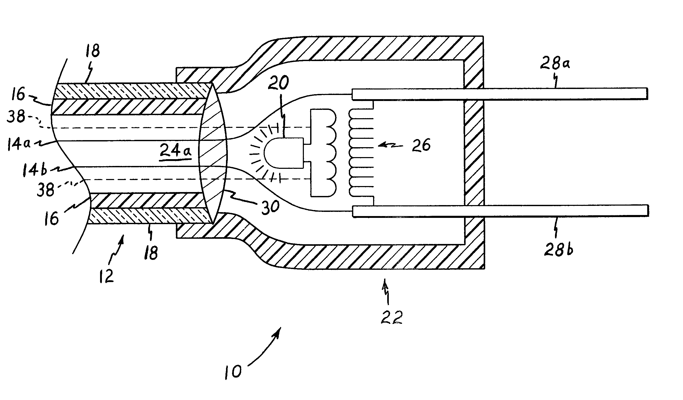
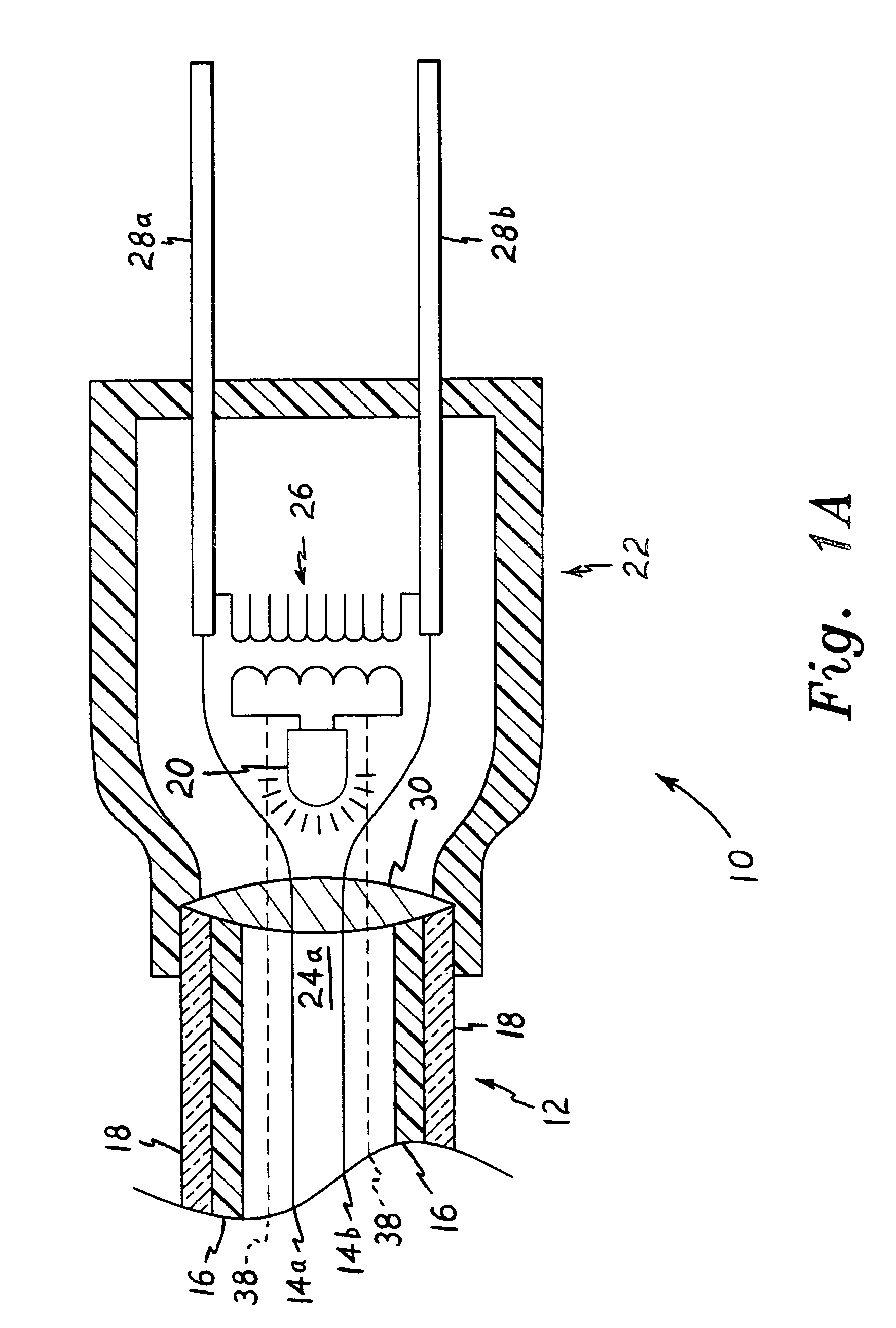
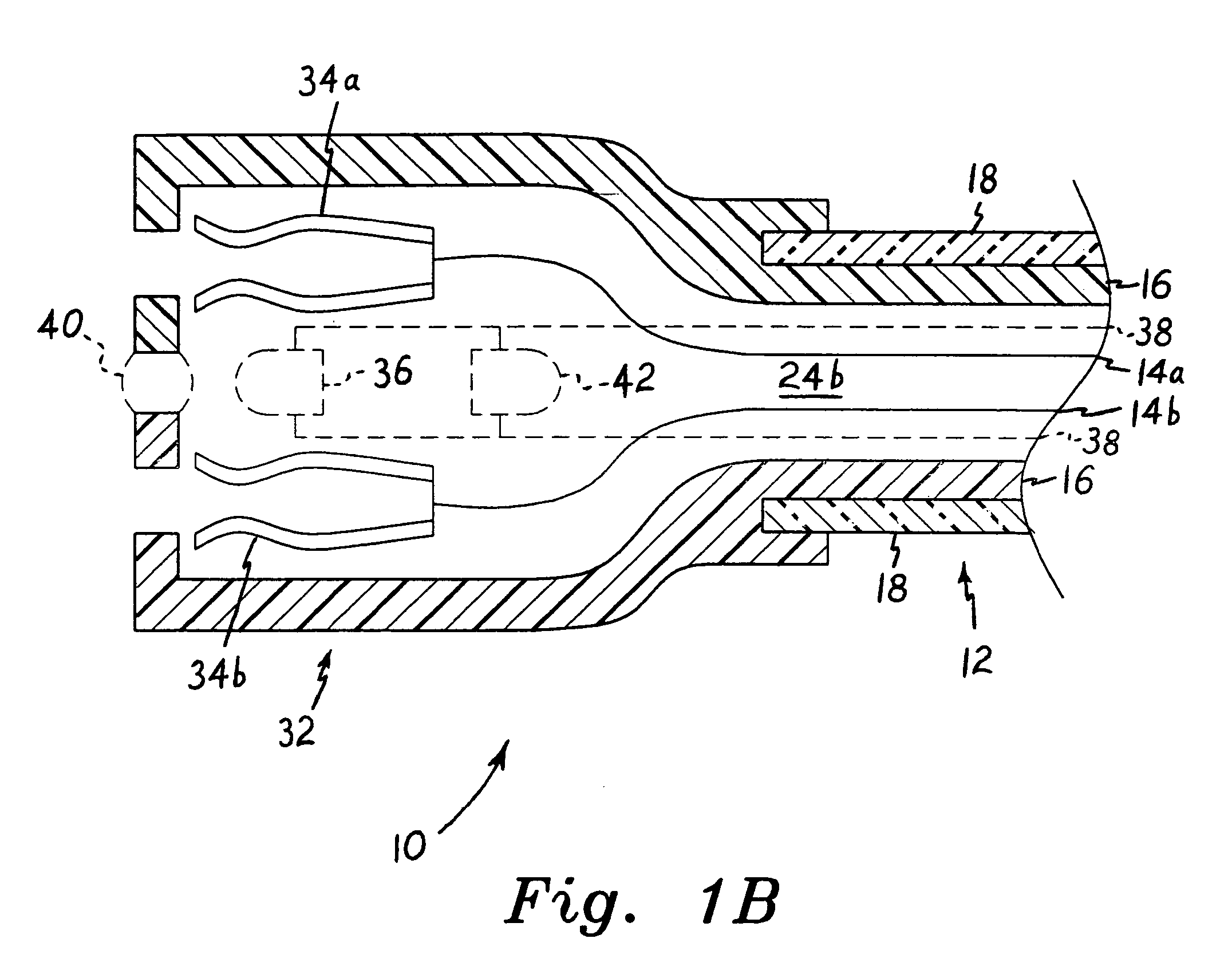
[0049]The present invention comprises illuminated electrical cords and illuminated electrical outlets therefor. In some of the embodiments of the present invention, the electrical cords include lighting means integrated within one or both of the end connectors of the cord. In other embodiments, the cords receive light output from the illuminated outlets of the present invention. In all cases, the illuminated cords have a translucent outer cover or sheath which emits light radially therefrom when light is transmitted into the translucent sheath from either or both ends thereof. The present cords are not only decorative when illuminated, but also serve to facilitate electrical connections of devices in poorly lighted areas. The present illuminated cords also provide significant safety advantages when used in otherwise unlighted areas, as their illumination makes them readily visible in order to mark their presence to allow persons to avoid tripping over such cords.

[0050]FIG. 1A of the...


PUM

PropertyMeasurementUnit
electrically insulatingaaaaaaaaaa
translucentaaaaaaaaaa
lengthaaaaaaaaaa

Abstract

A number of different embodiments of illuminated electrical cords and outlets are provided. Some embodiments include a light source within at least one connector end of an electrical cord, with the cord having a translucent outer cover for emitting the light radially from the connector end light source. The cord may be a household electrical or extension cord, a computer power supply cord, auxiliary power cord, etc., as desired. A kit may be provided to adapt a conventional, non-illuminated cord to provide illumination therefrom. Other embodiments include electrical outlets, adapters, and power strips having a light source(s) therein, for illuminating an electrical cord installed in the electrical power source. The outlets, adapters, and power strips may include differently colored lighting, and / or multiple colored lenses for manual or automated selection of color output. Battery power may be provided, with automated switching in the event of a primary power failure.

Description

REFERENCE TO RELATED PATENT APPLICATION[0001]This application claims the benefit of U.S. Provisional Patent Applications Ser. Nos. 60 / 356,978, filed on Feb. 14, 2002, and 60 / 363,606, filed on Mar. 12, 2002.BACKGROUND OF THE INVENTION[0002]1. Field of the Invention[0003]The present invention relates generally to electrical power cords and electrical outlets therefor, and more specifically to means for illuminating the cords substantially along their entire lengths. Illuminated outlets and connectors are also provided.[0004]2. Description of the Related Art[0005]Electrical and extension cords, power supply and data transmission cables, and other types of cords and cables carrying electrical energy and signals, conventionally comprise one or more internal conductors surrounded by an electrically insulating, opaque cover or sheath. In certain rare instances, a translucent or transparent outer cover or sheath has been provided for the electrical conductor(s) in such wiring. However, the ...

Claims


Application Information

Patent Timeline
Patent Type & Authority Patents(United States)
IPC IPC(8): F21V23/00C07D213/55C07D213/75C07D213/78C07D213/79C07D401/04C07D405/04C07D405/14C07D413/04C07D413/14C07D417/04C07D521/00
CPCH01R13/7172H01B7/36H01R13/7175Y10S362/80
Inventor CURRIE, ROBERT M.ROBERTSON, JONAS J.
Owner PLASTICS INVENTIONS & PATENTS INC
Learn More