Endodontic instrument

a technology of endodontic instruments and endoscopy, which is applied in the field of endodontic instruments, can solve the problems of undesirable attachment of clip b>22/b> to shaft b>14/b>, impair the angle of file insertion into the root canal, and impair so as to prevent an electrical short during use, improve the dexterity of file manipulation, and improve the effect of visibility

Inactive Publication Date: 2006-10-17
LAMPERT CHRISTOPHER
View PDF22 Cites 20 Cited by
  • Summary
  • Abstract
  • Description
  • Claims
  • Application Information

AI Technical Summary

Benefits of technology

[0009]In a first embodiment, the endodontic file of the present invention includes a connection assembly for an electronic apex locator wherein the connection is made at the coronal end of the file handle opposite the tapered cutting flutes. The file shaft extends through the handle so that a portion of the file shaft extends out of the coronal end of the handle. A clip or other mechanism is attached to the exposed shaft end to connect the electronic apex locator to the file. This connection assembly improves visibility and file manipulation.
[0012]In still another embodiment, the endodontic file includes a file shaft insulator located on the file shaft between the handle and the tapered cutting flutes for preventing an electrical short during use on a tooth with a metallic restoration.
[0013]The electronic apex locator connection assembly of this invention improves dexterity of file manipulation, improves visibility, improves tactile feedback, allows the electronic apex locator to be attached to the file at multiple angles, allows for the use of a file shaft insulator, and eliminates the use of a large traditional apex locator connection clip which creates a lever on the file shaft. These improvements make root canal procedures more accurate and efficient for both the practitioner and the patient.

Problems solved by technology

One problem of the assembly shown in FIG. 2 is that clip 22 is typically attached to shaft 14 between tapered cutting flutes 12 and handle 16 forming a 90° angle lever on shaft 14.
This location of attachment of clip 22 to shaft 14 is undesirable because it impairs visibility.
Such forces impair the dexterity of file manipulation and impair the angle of file insertion into the root canal.

Method used


Image

  • Endodontic instrument
  • Endodontic instrument
  • Endodontic instrument

Examples


Embodiment Construction

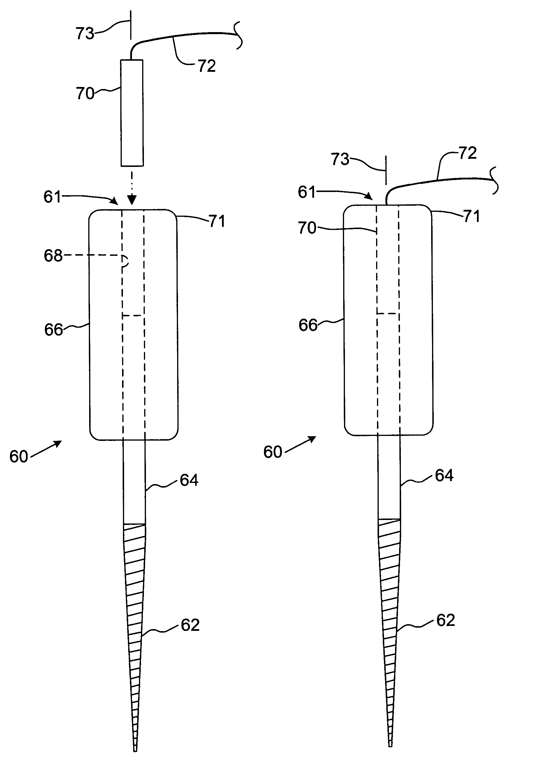
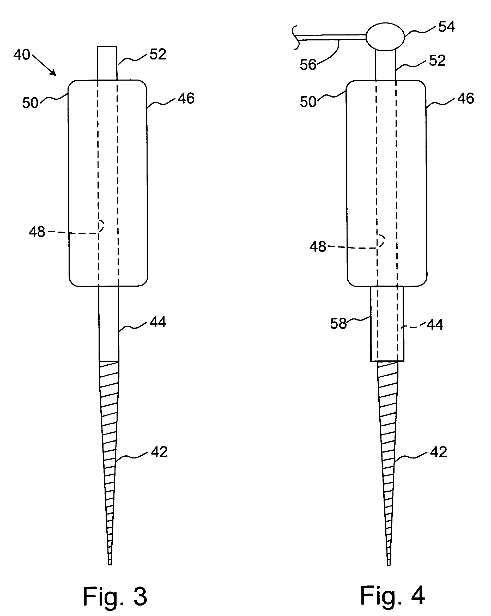
[0027]A first embodiment of an endodontic file of the present invention is shown in FIGS. 3 and 4 having a connection assembly for an endodontic file and an electronic apex locator wherein the connection is made at one end of the file handle. Endodontic file 40 is shown as an elongate element having tapered cutting flutes 42 comprising a working end for insertion into a root canal (not shown) and a shaft 44 secured to a handle 46 to be grasped by a user. Shaft 44 is secured by any convenient means to handle 46. Preferably, shaft 44 extends through and is held within a central opening 48 in handle 46. As seen most clearly in FIG. 3, shaft 44 extends past a coronal end 50 of handle 46 resulting in an exposed portion 52 to which the electronic apex locator is attached.

[0028]As shown in FIG. 4, exposed portion 52 provides a connection site for a connector 54 for an electronic apex locator. Connector 54 includes a conductor such as, for example, an electrical wire 56 as best seen in FIG....


PUM


Abstract

An endodontic instrument for root canal treatment is provided having a working portion manipulated by a handle and a connection assembly for attachment with an electronic apex locator. The connection assembly allows the electronic apex locator to be connected to the instrument at or through the coronal end of the handle. Preferably, the connection assembly includes a male / female assembly located within or on the surface the file handle.

Description

CROSS-REFERENCE TO RELATED APPLICATIONS[0001]This application is a continuation of International PCT application No. PCT / US2003 / 02072, filed Jan. 22, 2003, which claims priority to and the benefit of U.S. Provisional Patent Application Ser. Nos. 60 / 352,610, filed Jan. 28, 2002; 60 / 387,214, filed Jun. 10, 2002; and 60 / 411,641, filed Sep. 18, 2002, the entire disclosures of which are hereby incorporated by reference as if recited in full herein for all purposes.FIELD OF THE INVENTION[0002]This invention relates generally to endodontic instruments for performing root canal procedures and, more particularly, to a connection assembly for electrically connecting an endodontic file to an electronic apex locator.BACKGROUND OF THE INVENTION[0003]Traditional endodontic files consist of a tapered cutting flute portion having a shaft connected to a handle that is gripped by a user such as, for example, a dentist or an endodontist. Endodontic files are used to remove the contents of a root canal...

Claims


Application Information

Patent Timeline
Patent Type & Authority Patents(United States)
IPC IPC(8): A61C5/02A61C19/04
CPCA61C5/023A61C5/025A61C19/041A61C5/42A61C5/44
Inventor LAMPERT, CHRISTOPHER
Owner LAMPERT CHRISTOPHER
Why Eureka
Try Eureka