Device for reducing the gas and water contamination of transformer oil filling

a transformer oil and water contamination technology, applied in the direction of transformer/inductance cooling, liquid degasification with magnetic field, structural/machine measurement, etc., can solve the problems of substantially restricted above mentioned disadvantages, achieve high stability, reduce undesirable admixture infiltration, and obstruct the requested fluid mixing very effectively

Inactive Publication Date: 2006-10-17
ALTMANN JOSEF
View PDF10 Cites 10 Cited by
  • Summary
  • Abstract
  • Description
  • Claims
  • Application Information

AI Technical Summary

Benefits of technology

[0015]The above mentioned disadvantages are substantially restricted by means of the device for reducing the gas and water contamination of fluids consisting of a main tank and a conservator which is provided with a sludge discharge fitting. These are mutually joined by an upper connecting pipe in which a Buchholz relay and a discharge fitting are built. The main tank top part is joined with the oil cooler top part by an upper pipe coupling in which a circulating pump is built. The oil cooler bottom part is joined by a lower pipe coupling with the bottom part of the main tank which is also provided with a release fitting.
[0020]The advantage of the device according to the invention consists above all in the fact that the clean and hot fluid in a main vessel, heated by a thermal source, is separated by a stable thermal stratifying layer, which arises spontaneously in an external, so called stabilizing tank, from cold and potentially contaminated fluid from the conservator. At the same time, the stratifying layer position and stability are controlled by transformer cooling.
[0022]The influence of these layers is mostly held as negative phenomenon because these layers are very stable and obstruct the requested fluid mixing very effectively. On the contrary, in the device according to the inventions this phenomenon and its relatively high stability are utilized to reduce the undesirable admixture infiltrations into the protected fluid.

Problems solved by technology

The above mentioned disadvantages are substantially restricted by means of the device for reducing the gas and water contamination of fluids consisting of a main tank and a conservator which is provided with a sludge discharge fitting.

Method used


Image

  • Device for reducing the gas and water contamination of transformer oil filling
  • Device for reducing the gas and water contamination of transformer oil filling
  • Device for reducing the gas and water contamination of transformer oil filling

Examples


Embodiment Construction

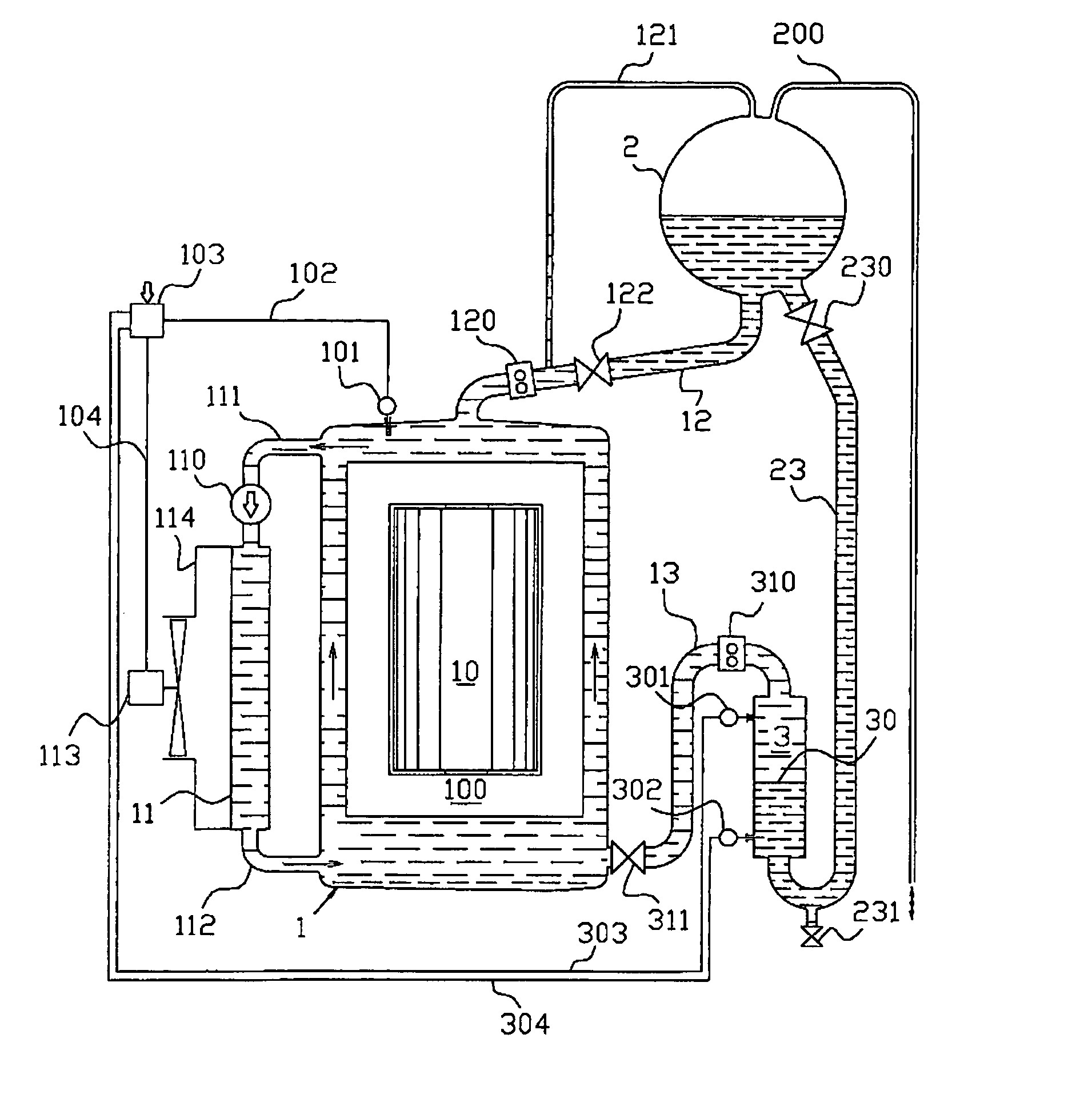
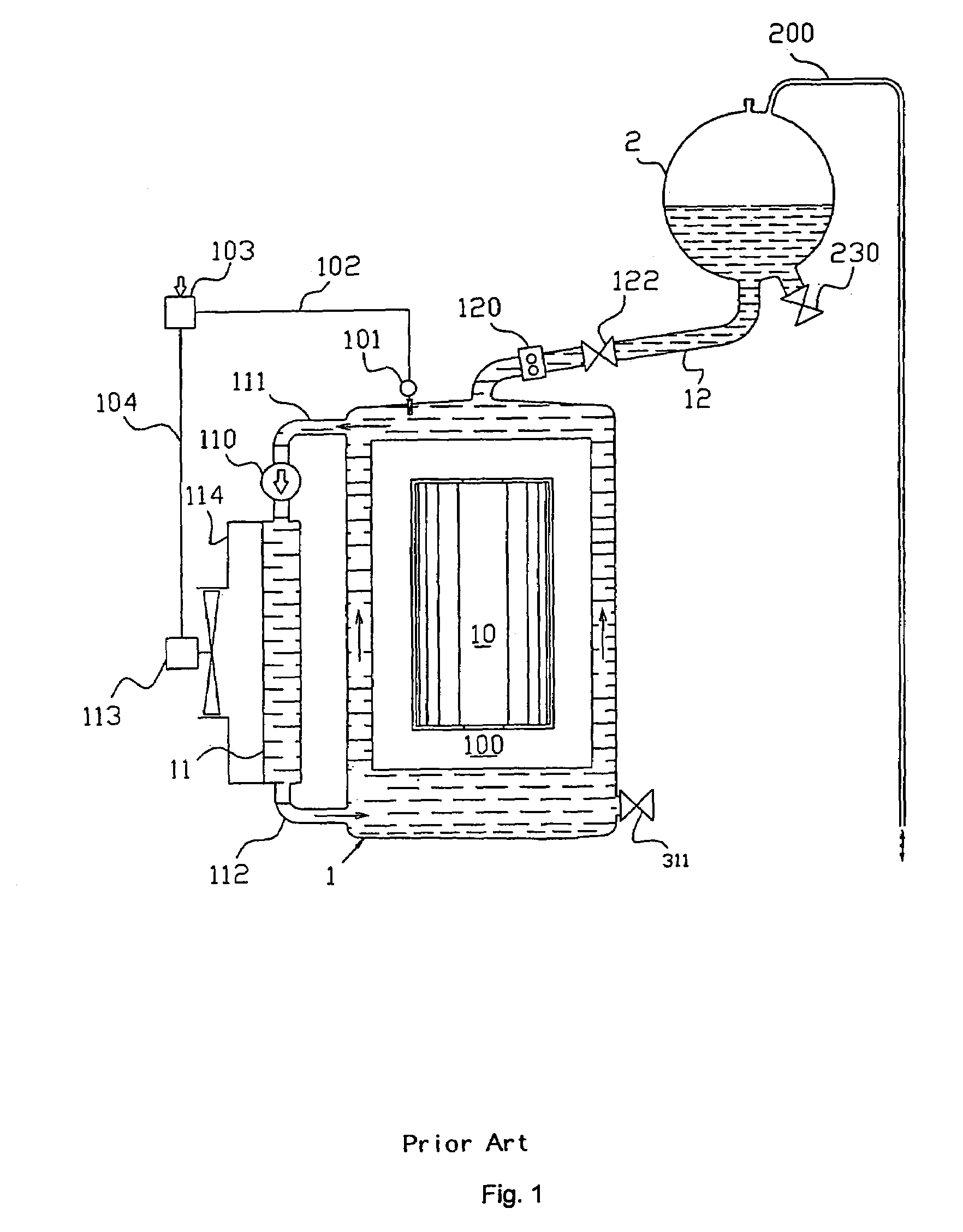
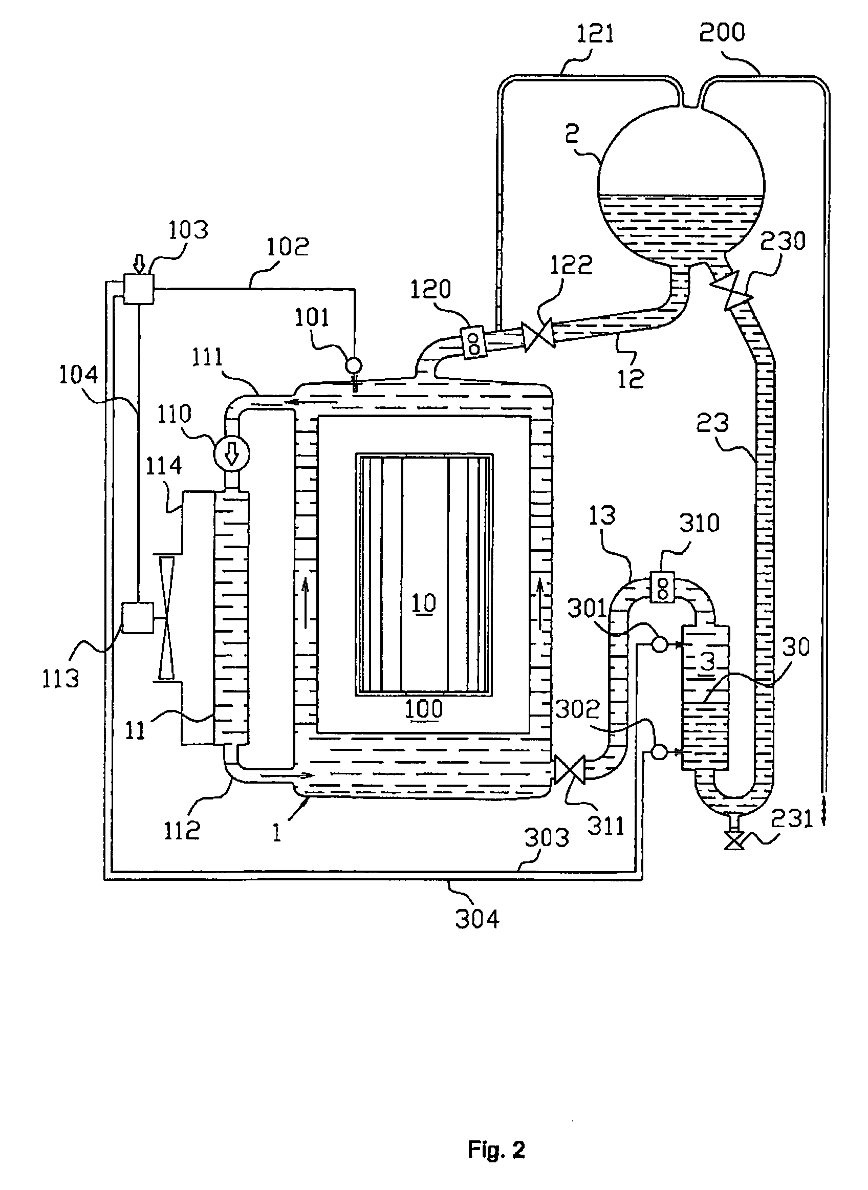
[0025]On of the practical embodiments according to the invention is given on the attached drawing in FIG. 2 where the device in accordance with the invention is presented as a modification to the usual power transformer, the standard arrangement of which is shown in FIG. 1.

[0026]An example of the device arrangement in accordance with the invention conforming to FIG. 2 primarily includes a main tank 1, and a conservator 2 located above the main tank 1 and the stratification or stabilizing tank 3. In part, the lower part of the conservator 2 is joined with a lower part of said stabilizing tank 3 by means of a lower connecting pipe 23. An upper part of the stabilizing tank is joined by a connection 13 for conveying hot oil with a lower part of the main tank 1 of a transformer. The lower part of the conservator 2 is in part joined with the upper part of the main tank 1 by an upper connection pipe 12 where the upper Buchholz relay 120 and the discharge fitting or cut-off valve 122 are si...


PUM

PropertyMeasurementUnit
air humidityaaaaaaaaaa
humidityaaaaaaaaaa
elasticaaaaaaaaaa

Abstract

The device for reducing the gas and water contamination of transformer oil filling includes a main tank and a conservator provided with a sludge discharge fitting, being joined by an upper connecting pipe having an upper Buchholz relay and a discharge fitting. A lower pipe coupling including a circulating pump joins a top part of the main tank with a top part of an oil cooler while a bottom part of the cooler is joined by a lower pipe coupling with the bottom part of the main tank. The main tank bottom part is provided with a release fitting and also has a connection led out from the release fitting, and is joined with the top part of a stabilizing tank, the bottom part of which is joined by a connection pipe with the sludge discharge fitting and / or with a fitting located in the conservator bottom part.

Description

BACKGROUND OF THE INVENTION[0001]1. Field of the Invention[0002]The invention relates to a device for reducing the gas and water contamination of transformer oil fillings which is especially suitable for reducing air gas and air humidity contamination of power transformers oil fillings.[0003]2. Description of the Related Art[0004]The existing solutions for reducing the gas and water contamination of fluids can be distinguished according to the principles they utilize on the one hand, or the degree of protection which these solutions give to protected fluids on the other hand.[0005]One of the examples well known from engineering practice is the protection of power transformer oil fillings against air gas and humidity infiltration from the surrounding atmosphere.[0006]The most frequently used devices are limited to only reducing the air humidity infiltration into the transformer oil filling by using air dryers. The dryers, operating either on an absorption or a freezing principle, are...

Claims


Application Information

Patent Timeline
Patent Type & Authority Patents(United States)
IPC IPC(8): B01D19/00H01F27/14B01D17/00B01D17/025B01D17/09B01D17/12B01D21/34H01F27/08H01F27/12
CPCB01D17/00B01D19/0042B01D19/0089B01D17/005B01D17/0208B01D17/0214H01F27/14B01D17/12
Inventor ALTMANN, JOSEF
Owner ALTMANN JOSEF
Why Eureka
Try Eureka