Analog multi-display using digital visual interface

a digital visual interface and multi-display technology, applied in the direction of instruments, electric digital data processing, cathode-ray tube indicators, etc., can solve the problems of limiting the usable bandwidth of dvi-i interface, analog displays, and inability to support dual head operation of analog displays

Inactive Publication Date: 2006-10-17
MATROX
View PDF8 Cites 46 Cited by
  • Summary
  • Abstract
  • Description
  • Claims
  • Application Information

AI Technical Summary

Benefits of technology

[0015]Accordingly, an aspect of the present invention provides a method of controlling a display monitor through a multi-channel coupler. The method comprises steps of: detecting a type of the display monitor, using at least one channel of the coupler; selecting a channel plan based on the detected display monitor type, the channel plan defining a connectivity between the channels of the coupler and a plurality of display control signals; and connecting each channel of the coupler in accordance with the selected channel plan.
[0016]Another aspect of the present invention provides an interface for controlling a display monitor through a multi-channel coupler. The interface comprises: a detector adapted to detect a type of the display monitor; a controller adapted to select a channel plan based on the detected display monitor type, the channel plan defining a connectivity between the channels of the coupler and a plurality of display control signals; and a switching means adapted to selectively connect each channel of the coupler in accordance with the selected channel plan.

Problems solved by technology

A limitation of the DVI-I standard interface is that dual head operation is not supported for analog displays.
Thus, even when a graphics card has sufficient bandwidth to support two displays, the DVI-I interface limits the usable bandwidth, for analog displays, to a single display.

Method used


Image

  • Analog multi-display using digital visual interface
  • Analog multi-display using digital visual interface
  • Analog multi-display using digital visual interface

Examples


Embodiment Construction

[0024]The present invention provides a method and interface for controlling a display monitor through a “multi-channel coupler” (connector), based on the display monitor type.

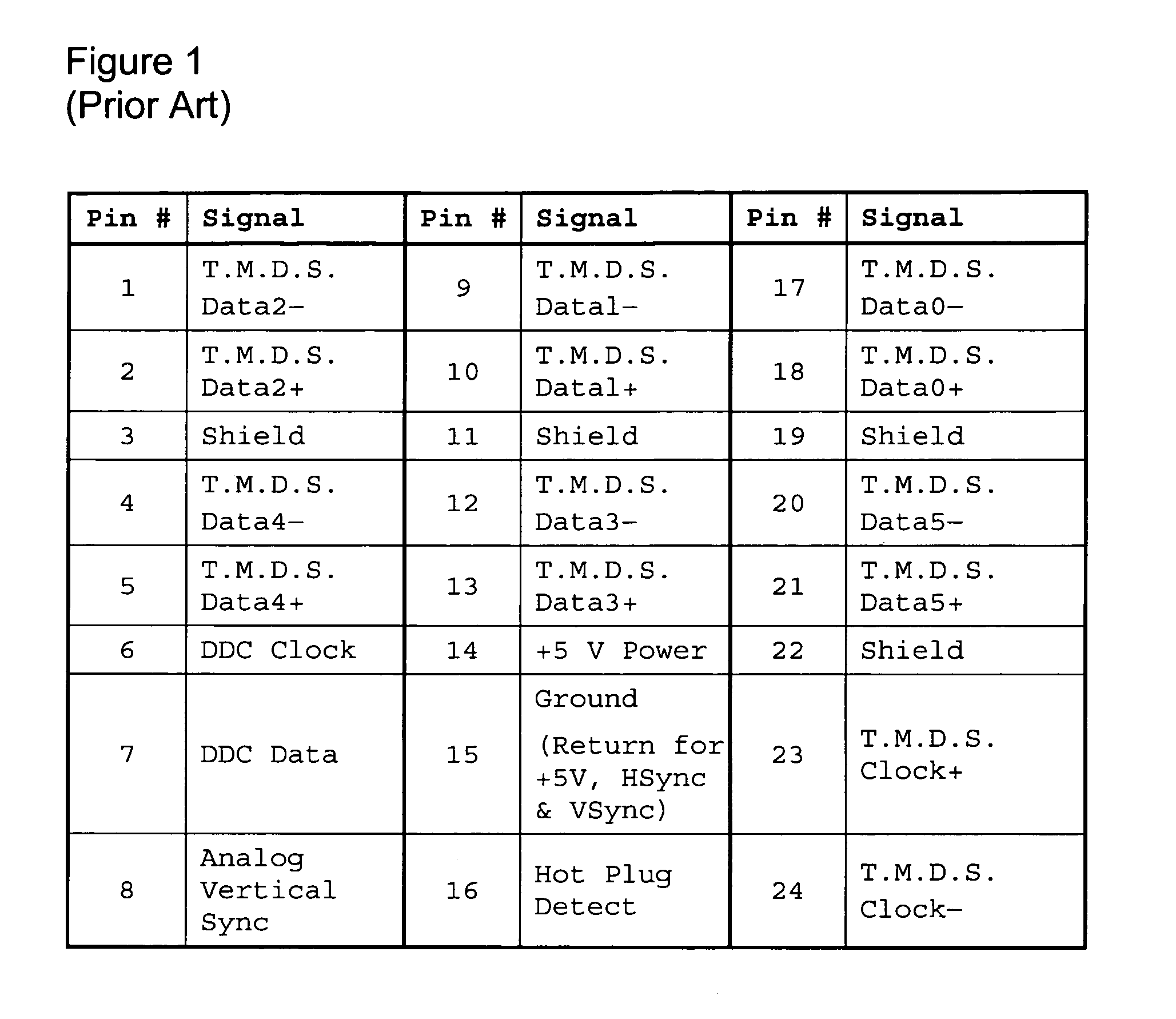
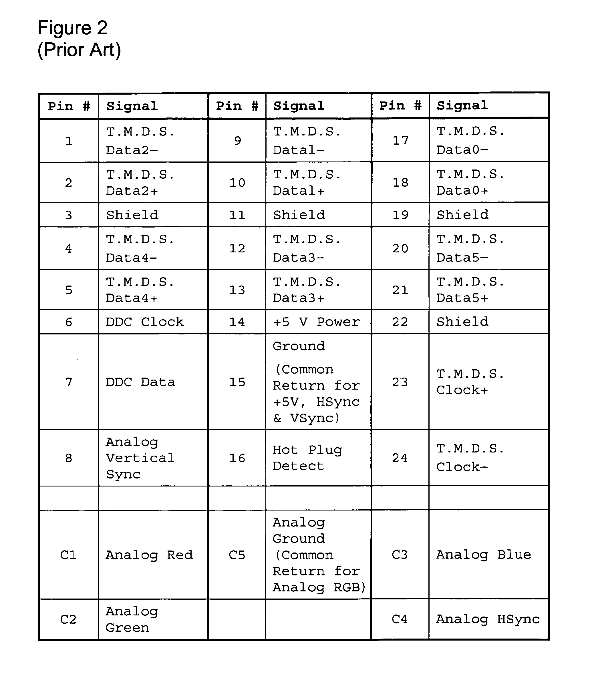
[0025]For convenience of description, the present invention is described herein by way of example, wherein a DVI-I compliant interface is extended to support dual analog display devices. Thus, a modified DVI-I compatible interface is presented which can support up to two DVI compatible display devices, or up to two VESA compatible analog display devices. However, those of ordinary skill in the art will appreciate that the present invention is by no means limited to such an embodiment.

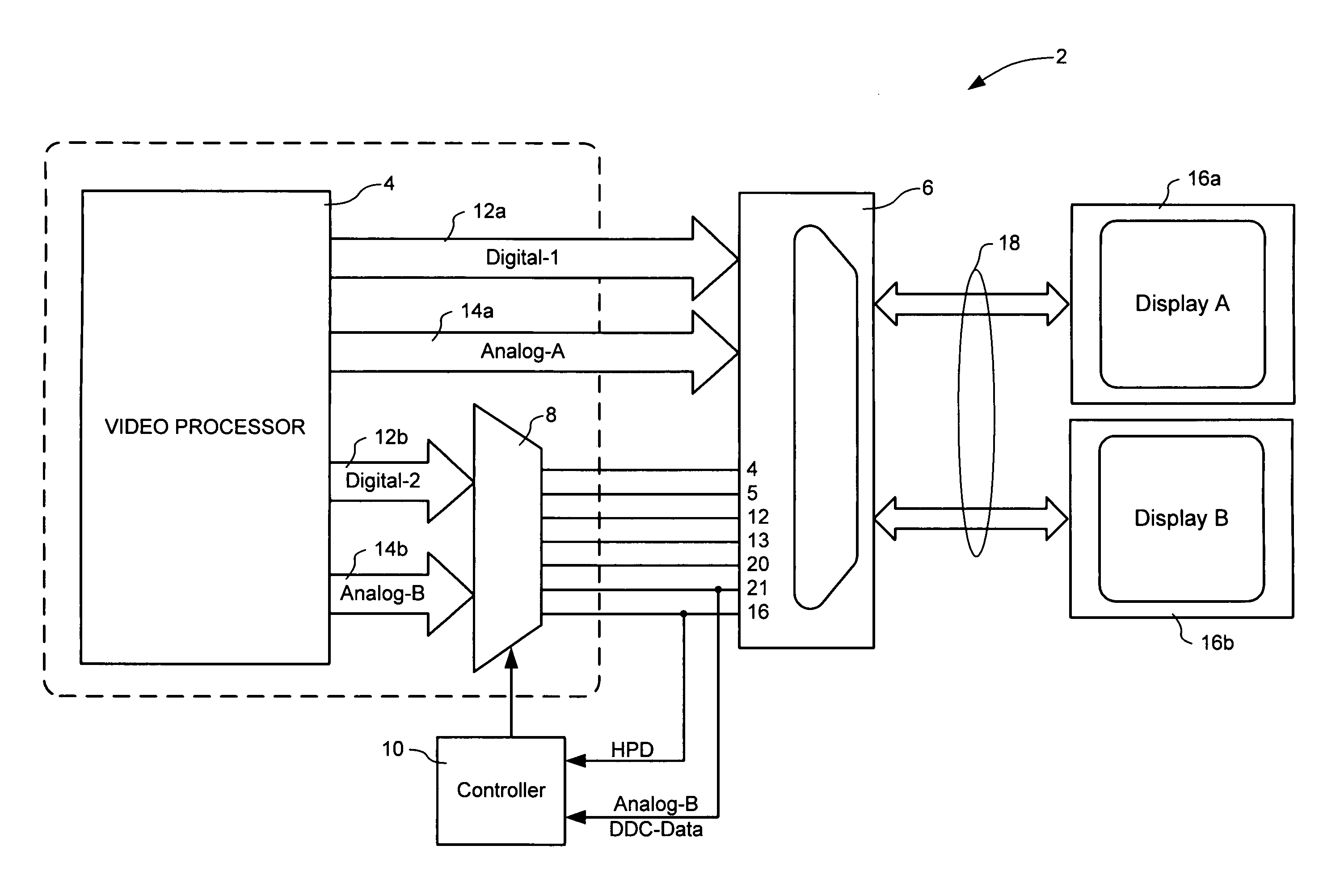
[0026]FIG. 3 illustrates principle elements of an exemplary interface 2 in accordance with the present invention. As shown in FIG. 3, the interface generally comprises a conventional video processor 4; a multi-channel coupler (e.g. a DVI-I compliant connector) 6; an enabler 8; and a controller 10. One or more display monitors 16 ca...


PUM


Abstract

A method and interface for controlling a display monitor through a multi-channel coupler detects a type of the display monitor and selects a channel plan defining a connectivity between the channels of the coupler, based on the type of the display monitor. The channel plan defines a connectivity between the channels of the coupler and a plurality of display control signals. Each channel of the coupler is connected in accordance with the selected channel plan. The display types can be for example analog or digital. The method and apparatus can be used to drive two analog display monitors from a DVI-I compliant interface.

Description

CROSS-REFERENCE TO RELATED APPLICATIONS[0001]This is the first application filed for the present invention.MICROFICHE APPENDIX[0002]Not Applicable.TECHNICAL FIELD[0003]The present invention relates to the field of display monitor interfaces, and in particular to a method and apparatus for controlling a display monitor through a multi-channel coupler.BACKGROUND OF THE INVENTION[0004]Computers have traditionally used cathode ray tubes (CRTs) for displaying information. CRTs are inherently analog in nature, and thus traditional video interfaces use analog signals to convey display data from a computer system to a display device. A popular standard is the Video Electronics Standards Association (VESA) RGB standard for analog display devices. VESA compliant analog monitors support VESA Display Data Channel (DDC) protocol for communicating the monitor functionality to a graphics control card.[0005]With the increasing popularity of flat panel display (FPD) technologies, (such as, for examp...

Claims


Application Information

Patent Timeline
Patent Type & Authority Patents(United States)
IPC IPC(8): G09G5/00
CPCG09G5/006G06F3/1431G09G2370/042G09G2370/047
Inventor LAFLEUR, ROBERT
Owner MATROX
Why Eureka
Try Eureka