Digital camera and power supply apparatus used therefor

a power supply apparatus and digital camera technology, applied in the field of digital camera and power supply apparatus, can solve the problems of power supply voltage drop, large load applied to the power supply, increased load power at the time of motor operation, etc., and achieve the effect of avoiding excessive load and low power supply capacity of the power supply apparatus

Inactive Publication Date: 2006-10-17
RICOH KK
View PDF6 Cites 29 Cited by
  • Summary
  • Abstract
  • Description
  • Claims
  • Application Information

AI Technical Summary

Benefits of technology

[0013]The present invention has been made in view of the above mentioned problems. Therefore, it is a first object of the present invention to provide a digital camera capable of eliminating a factor that interferes with operation of a camera, shortens the life of battery or hinders power saving and enhancing user convenience.
[0014]In addition, it is a second object of the present invention to provide a power supply apparatus suitable for the above digital camera which is low in cost and capable of achieving reduction of space and reducing a voltage variation by power saving, without undermining an electrical characteristic.

Problems solved by technology

As a result, load power at the time of operation of the motor is increased and hence a large load is applied to a power supply.
Accordingly, in the digital camera in which same power source is used with respect to those portions, there is a possibility that power supply voltage drops by increase in the load power of the motor and thereby operation of the digital camera itself cannot be carried out.
Even if the digital camera is barely operated in such case, the problem occurs that the life of battery is shortened in a case where a battery is used as the power supply.
However, this makes a period of operating the motor long.
Meanwhile, there are three reasons for generation of a voltage variation in the power supply due to load fluctuation, first, for lack of supply capacity of the power supply, second, for lack of conversion capacity of a power conversion circuit in the power supply, and third, for too much loads.
Among these reasons, it can be said that the lack of capacity of the power conversion circuit is the major technological issue with respect to the power supply.
However, in the rapid change of the load, for example if the load is increased drastically, the output voltage falls since the power cannot be supplied sufficiently, whereas if the load is decreased drastically, the output voltage rises due to excessive supplying of power.
However, there is a limitation in terms of software and hardware to allow the oscillation cycle to be faster, and 100% is the limitation to make “ON-duty” to be longer in the changing of the duty, thus the fall of the output voltage cannot be suppressed at some point.
Therefore, it can be said that the operational limitation in terms of the software and the hardware is the limitation of the capacity in the power conversion circuit.
However, use of the large capacity of condenser causes various adverse effects to generate such as increase of rush current, delay in rising and falling, rise in cost and increase in mounting spaces.
In addition, there is a limitation to make the response of the feedback of the output faster, and even if the acceleration of the response in the feedback of the output is obtained, there is a problem that power consumption increases significantly because the response is accelerated.
Also, since the conventional technique disclosed in the above mentioned JP-A H6-119074 is the technique which carries out the feedback by regarding that the degree which the load fluctuates is the alternating current-like variation, and there is the limitation in order to accelerate the response in the feedback of the output, it also has the problem similar to the above described conventional technique.

Method used


Image

  • Digital camera and power supply apparatus used therefor
  • Digital camera and power supply apparatus used therefor
  • Digital camera and power supply apparatus used therefor

Examples


embodiment 1

[0074]Hereinafter, a digital camera according to the present invention will be described in detail in accordance with embodiment 1 shown in the drawings. However, it should be noted that structural elements, kinds, combinations, configurations or their relative arrangements described in this embodiment are merely illustrative by way of example, thus it is not intended to limit the scope of the present invention by them unless otherwise specifically stated.

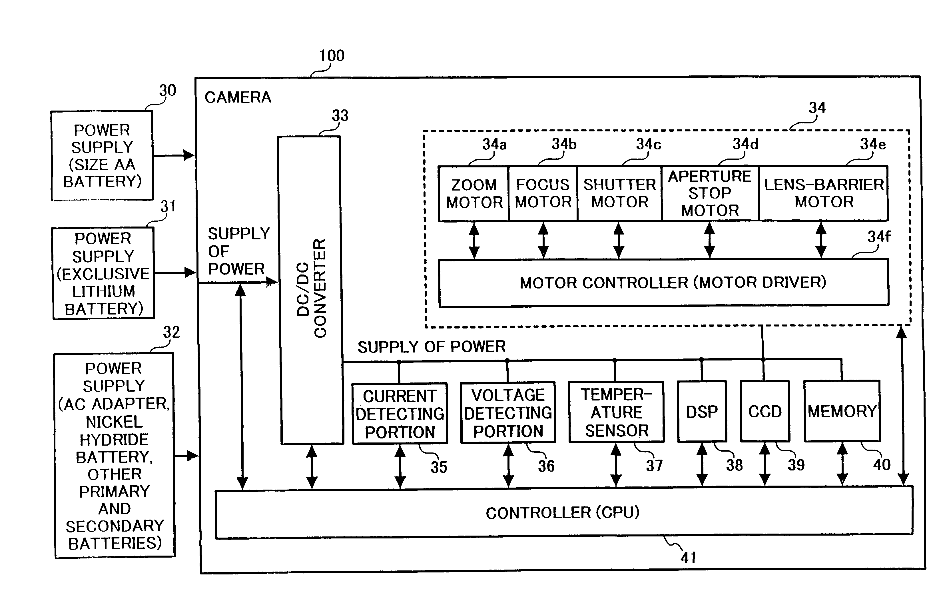
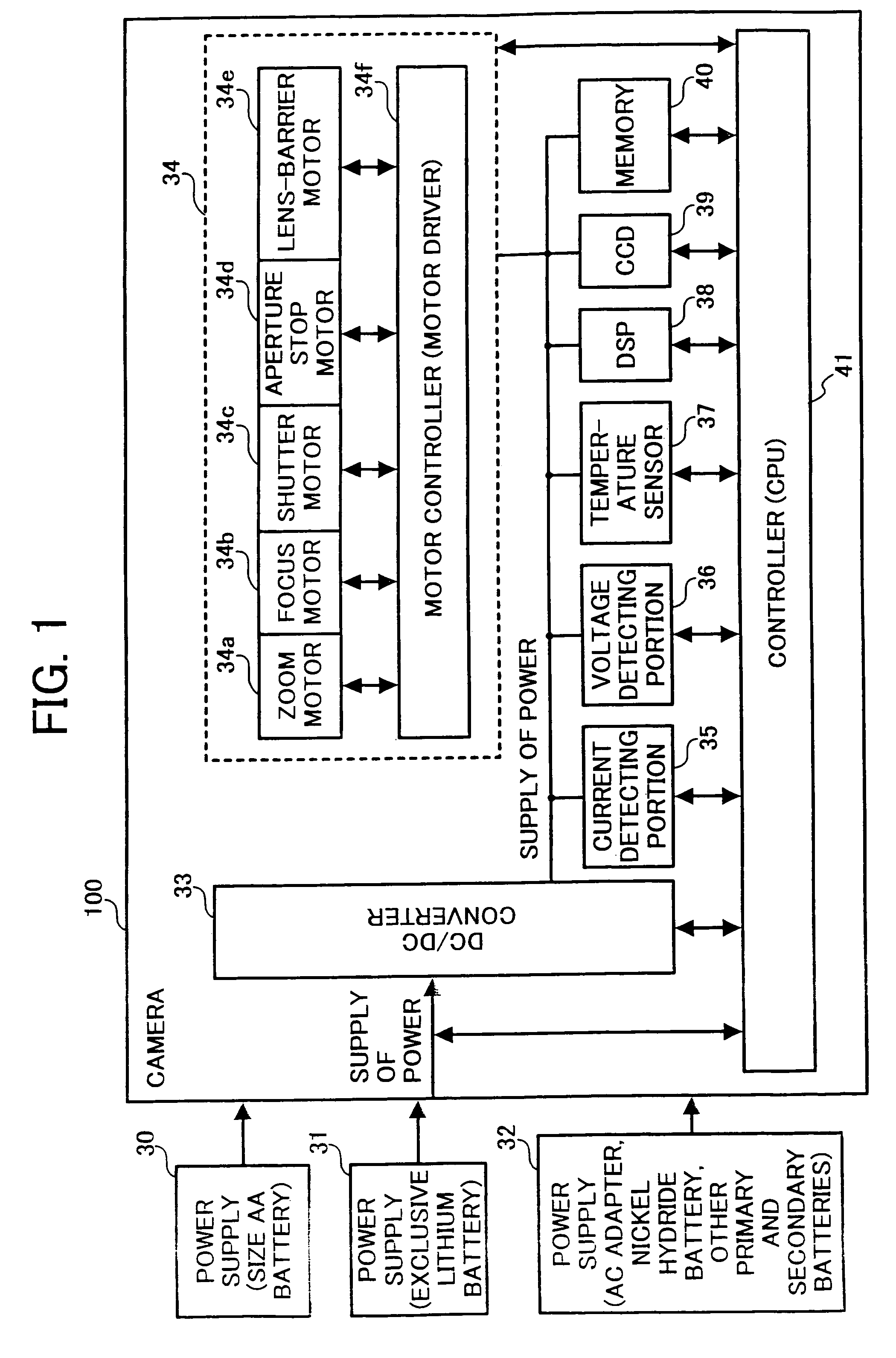
[0075]FIG. 1 is a block diagram of a digital camera according to embodiment 1 of the present invention. The digital camera 100 comprises a size AA battery 30, an exclusive lithium battery 31 being used exclusively for the digital camera 100, an AC adapter 32 which are power supplies, a DC / DC converter 33 which converts power voltage to generate various voltage necessary for the camera, a motor portion 34 which includes various motors and controls them, a current detecting portion 35 for detecting current flowing from the DC / DC conv...

embodiment 2

[0096]FIG. 4A is a diagram showing the power supply apparatus according to the embodiment 2, which comprises a power supply 201 constructed by a battery or an AC adapter or the like, a power conversion circuit 202 (moderation mechanism) for converting the power from the power supply 201 into predetermined voltage and controlling the supplying of power according to increase and decrease of a load by monitoring the output voltage, a main load 203 which structures a principal load such as a motor and an electronic circuit and so on, an artificial load 205 structured by a load which is lighter in load than the main load 203, and an artificial load controlling portion 204 for connecting the artificial load 205 with the main load 203 and disconnecting the artificial load from the main load 203. Meanwhile, although it is described here as if the artificial load controlling portion 204 is controlled by the power conversion circuit 202, the artificial load controlling portion may be controll...

embodiment 3

[0097]FIG. 4B is a diagram showing the power supply apparatus according to the embodiment 3. In this embodiment, since the same reference numeral is attached to the component part similar to the above embodiment, the overlapping explanation will be omitted here. The points that FIG. 4B differs from FIG. 4A are that the artificial load shown in FIG. 4A has turned into artificial loads 207–208 having different amount of loads, respectively, and an artificial load controlling portion 206 selects either one of those artificial loads. More specifically, normally, the load varies according to each output system in the power supply in which a plurality of output systems exists. In such case, it is necessary to optimize the artificial loads in accordance with size of the load. Therefore, the present embodiment includes a plurality of artificial loads 207–208 having the various kind of amount of load, and selects the most suitable artificial load with the artificial load controlling portion ...


PUM


Abstract

A digital camera, including a common power supply for supplying power; a plurality of motors sharing the power supply and driven by the power supplied from the power supply; and a current detector for detecting load current supplied to the plurality of motors, wherein, when either one of the plurality of motors is operated, other motor is driven not to overlap with a maximum value of the load current detected by the current detector.

Description

BACKGROUND OF THE INVENTION[0001]1. Field of the Invention[0002]The present invention relates to a digital camera and a power supply apparatus suitable therefor.[0003]2. Description of the Related Art[0004]Recently, a digital camera has been used often in place of a conventional camera utilizing a film. Additionally, in the digital camera, it has been aimed to allow a lens-barrier motor, a zoom motor and a focus motor and the like to complete their predetermined operation as soon as possible at the time of activation or photographing to reduce the time lag and thereby to enhance user convenience. As one of the ways to accomplish the aim, for example, motor driving power is increased to drive the motor at high speed, or a plurality of motors is driven simultaneously, to achieve reduction of operating time of the camera. As a result, load power at the time of operation of the motor is increased and hence a large load is applied to a power supply.[0005]As conventional technique to redu...

Claims


Application Information

Patent Timeline
Patent Type & Authority Patents(United States)
IPC IPC(8): G03B7/26G05F1/10H02H7/00H02J1/00H04N5/232
CPCH04N5/232H04N5/23241H04N23/651
Inventor OHSUGA, JUN
Owner RICOH KK
Why Eureka
Try Eureka