Cell Cartridge with a Composite Intercell Connecting Net Structure

a cell cartridge and net structure technology, applied in the field of cell cartridges, can solve the problems of inaccuracy of battery pack manufacturing standards, a large amount of time required for processing, and a large number of defects, so as to improve assembly and production efficiency, shorten the time required for assembly, and increase the accuracy of manufacturing standards

Inactive Publication Date: 2011-11-24
ICEL SYST KOREA +1
View PDF0 Cites 31 Cited by
  • Summary
  • Abstract
  • Description
  • Claims
  • Application Information

AI Technical Summary

Benefits of technology

[0030]Therefore, the cell cartridge of the present invention provides the following effects.
[0031]1. Since the unit cells can be simply assembled in the cell cartridge, as opposed to the conventional methods of binding the unit cells with glass tape, for example, it is possible to shorten the time required for assembly and improve the assemblability and productivity. Moreover, since the cells are accommodated and assembled in a predetermined frame of the case, it is possible to increase the accuracy of manufacturing standards, compared to the process of simply binding the cells.
[0032]2. With the use of the spacing members, the cells can be spaced at regular intervals, and thus the cells are not in contact with each other. Therefore, it is possible to prevent the problems caused by the direct contact between the cells and by the heat generated thereby. That is, it is possible to solve the problems such as the interaction between the cells due to the heat transfer, the reduction in operating efficiency, and the reduction in lifespan of the battery.
[0033]3. With the modification of the structure of the external terminals connected to the cell terminals, it is possible to prevent a contact failure or excessive contact resistance between the cell terminals and the external terminals.
[0034]4. Since the connection of the cell terminals is not made by welding, it is possible to solve the problems, such as welding defects, inconvenience of welding process, excessive assembly time due to the welding, degradation of assemblability and productivity, etc. Especially, the cells can be simply accommodated in the case to which the connection plates are preassembled, and the electrodes at both ends of the respective cells accommodated in the case can be securely connected to the terminals of the connection plates without welding. Therefore, it is possible to eliminate the process of welding the nickel plates used as the connection plates to the electrodes at both ends of the respective cells, thereby enabling mass production, compared to the use of the welded nickel plates. Moreover, according to the conventional cell cartridge in which the nickel plates are welded to the cells, when any nickel plate is improperly welded or a certain cell needs to be repaired or replaced in the event of a failure, the corresponding nickel plate welded to the cells and the taping on the cells should be disassembled (that is, the disassembled cells and nickel plate should be discarded, which increases the cost, and the process of welding the nickel plate to the cells and taping the cells should be repeated). However, according to the cell cartridge of the present invention, only the defective cell can be easily replaced, and thus the time and cost for the repair and recovery can be reduced. That is, since the defective cell can be simply removed from the case and a new cell can be replaced, the replacement is easy to do.
[0035]5. According to the cell cartridge of the present invention, in which the connection plates are alternately arranged such that the cells in different rows are connected in series while the cells in the same row are connected in parallel, it is possible to construct a composite series-parallel connection network (with a compounded interconnection) only by accommodating the cells in the case.

Problems solved by technology

However, such a manufacturing process requires a lot of time and may produce a number of defects.
Moreover, the manual process may lead to inaccuracies in the manufacturing standards for the battery packs.
Especially, since the cells are in direct contact with each other, there is no sufficient shock absorption between the cells, and the heat generated is transferred to each other during discharge to cause interaction between the cells, which results in a significant reduction in operating efficiency, thereby reducing the lifespan of the battery.
Moreover, in the case where the cells are simply bound to each other with glass tape, a contact failure or excessive contact resistance between cell terminals and external terminals may occur due to position errors between the cells bonded to each other with the glass tape.
Moreover, there are many other problems such as the inconvenience of welding process, excessive assembly time due to the welding, degradation of assemblability and productivity, etc.
As a result, the disassembled cells and nickel plate should be discarded, which increases the cost and the process of welding the nickel plate to the cells and taping the cells should be repeated.

Method used


Image

  • Cell Cartridge with a Composite Intercell Connecting Net Structure
  • Cell Cartridge with a Composite Intercell Connecting Net Structure
  • Cell Cartridge with a Composite Intercell Connecting Net Structure

Examples


first embodiment

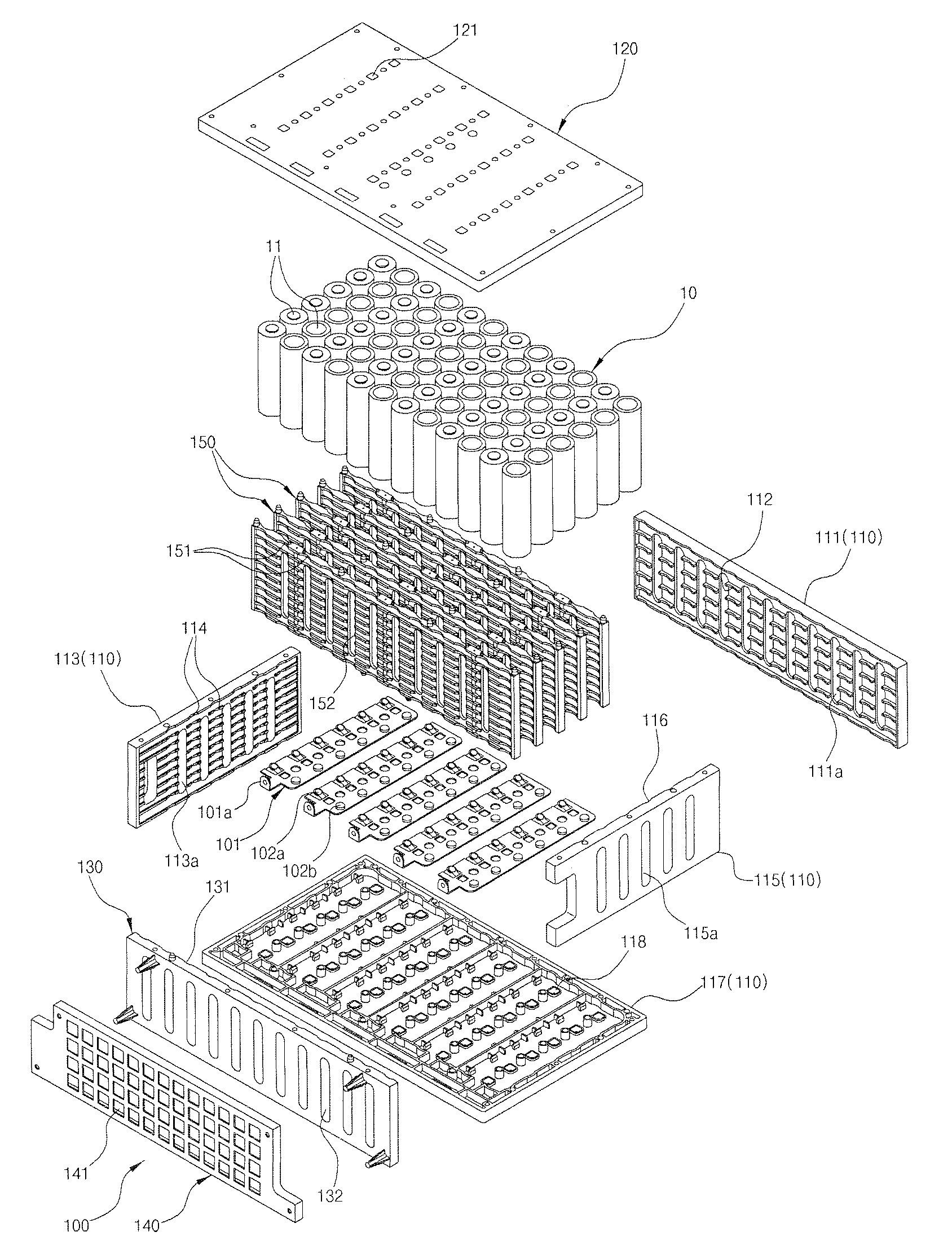
[0107]FIG. 14 is a cross-sectional view showing a connection plate terminal structure in accordance with the present invention, in which the terminal 102a connected to the negative electrode and the terminal 102b connected to positive electrode have different shape to ensure the connection of the cells 10.

[0108]First, the terminal connected to the negative electrode of the cell 10 comprises an elastic terminal plate 102a. As shown in FIG. 14, the elastic terminal plate 102a with a Z-shaped plate spring is fixedly inserted into to the connection plate 101 such that the top of the elastic terminal plate 102a is elastically connected to the negative electrode of the cell 10. The elastic terminal plate 102a is formed of an elastic conductive metal plate.

[0109]Preferably, the bottom of the elastic terminal plate 102a is fixed to the rear of the connection plate 101 by spot welding, for example, such that the elastic terminal plate 102a can be fixedly secured to the connection plate 101. ...

second embodiment

[0115]FIG. 16 is a cross-sectional view showing a connection plate terminal structure in accordance with the present invention, in which each of the connection plates 101 fixedly mounted on the case body and the upper cover, respectively, comprises a plurality of terminals 102 formed of a conductive material and projecting to connect to cell terminals 11 (i.e., electrode). Here, a magnet 103 is inserted in the middle of each of the terminals 102 of the connection plate 101.

[0116]As a result, the cell terminal 11 is attached to the magnet 103 such that the connection plate terminal 102 can be firmly connected to the cell terminal 11. That is, since both the terminals 11 and 102 are attached to each other by the magnetic force of the magnet 103, the contact state between the case terminals 102 (i.e., connection plate terminals) and the terminals 11 of the cells 10 accommodated in the case can be securely maintained, even when an external vibration is applied thereto.

third embodiment

[0117]FIG. 17 is a cross-sectional view showing a connection plate terminal structure in accordance with the present invention, in which the surface of the connection plate terminal 102 to be in contact with the cell terminal 11 has a round embossed pattern such that the connection plate terminal 102 can be in uniform contact with the cell terminal 11.


PUM

PropertyMeasurementUnit
distanceaaaaaaaaaa
angleaaaaaaaaaa
electrical energyaaaaaaaaaa

Abstract

The present invention provides a cell cartridge with a composite cell interconnection network, in which plural unit cells are assembled and modularized in a case in a composite series-parallel connection manner. An object of the present invention is to provide a cell cartridge with a composite cell interconnection network, in which a plurality of unit cells can be simply assembled, as opposed to conventional methods of binding the unit cells with glass tape, for example, to shorten the time required for assembly, improve assemblability and productivity, and increase the accuracy of manufacturing standards. Moreover, another object of the present invention is to provide a cell cartridge with a composite cell interconnection network, in which a plurality of unit cells are spaced at regular intervals to prevent problems caused by direct contact between the cells and by heat generated thereby, prevent problems such as cell performance degradation and reduced battery lifespan caused by the direct contact and the generated heat, and enable mass production of standardized and modularized battery packs. Furthermore, still another object of the present invention is to provide a cell cartridge with a composite cell interconnection network, in which the structure of external terminals connected to cell terminals is modified to prevent a contact failure or excessive contact resistance between the cell terminals and the external terminals, and which can solve many other problems, caused by the welding of a nickel plate in conventional methods, such as welding defects, inconvenience of welding process, excessive assembly time due to the welding, degradation of assemblability and productivity, etc. To this end, a cell cartridge with a composite cell interconnection network is disclosed, the cell cartridge comprising: a plurality of unit cells; a case which accommodates the unit cells and is then assembled; a plurality of spacing members, each disposed between the unit cells accommodated in the case to space the unit cells a predetermined distance from each other; and a plurality of connection plates fixedly mounted on an inner side of the case and each including terminals connected to electrodes of the respective unit cells to connect the electrodes of adjacently arranged cells to each other, wherein the unit cells are connected to each other by the connection plates connected to the respective electrodes in a composite series-parallel connection manner.

Description

TECHNICAL FIELD[0001]The present invention relates to a cell cartridge and, more particularly, to a cell cartridge in which a plurality of unit cells are assembled and modularized in a case.BACKGROUND ART[0002]A conventional lithium ion cell pack as an example of a storage battery, a kind of secondary battery, for storing electrical energy and supplying the electrical energy to a load will be briefly described below. First, a plurality of lithium ion cells capable of charging and discharging are combined into a unit module, a plurality of unit modules are combined into a larger module, and a plurality of larger modules are combined into a much larger module, thus manufacturing a battery pack having a desired capacity.[0003]In this case, cells having a circular cross-section (i.e., cylindrical cells) or cells having a square cross-section are bound to each other with glass tape, for example, to form a unit module and a plurality of unit modules are combined appropriately with glass t...

Claims


Application Information

Patent Timeline
Patent Type & Authority Applications(United States)
IPC IPC(8): H01M2/10H01M2/12H01M50/209H01M50/213H01M50/271H01M50/284H01M50/289H01M50/509
CPCH01M2/1077H01M10/503H01M10/5004H01M2/202H01M10/643H01M10/613Y02E60/10H01M50/209H01M50/213H01M50/284H01M50/509H01M50/271H01M50/289
Inventor KANG, JEONG WOOK
Owner ICEL SYST KOREA
Why Eureka
Try Eureka