Magnetic transducer torque measurement

a technology of magnetic transducer and torque measurement, which is applied in the field of torque measurement, can solve problems such as the non-uniformity of magnetisation about the rotation axis, and the inability to accurately measure the torque of the sha

Inactive Publication Date: 2006-10-24
ABAS
View PDF6 Cites 20 Cited by
  • Summary
  • Abstract
  • Description
  • Claims
  • Application Information

AI Technical Summary

Problems solved by technology

However, in practice problems can arise in making accurate torque measurements of a shaft due to sensitivity to axial displacements of the shaft.
Another problem which arises in exploiting longitudinally magnetised transducer elements in general is that the annular magnetisation created by relative rotation between a member, such as a shaft, and a magnetic source (permanent or electromagnet) may result in a non-uniformity of magnetisation about the axis of rotation.

Method used


Image

  • Magnetic transducer torque measurement
  • Magnetic transducer torque measurement
  • Magnetic transducer torque measurement

Examples


Embodiment Construction

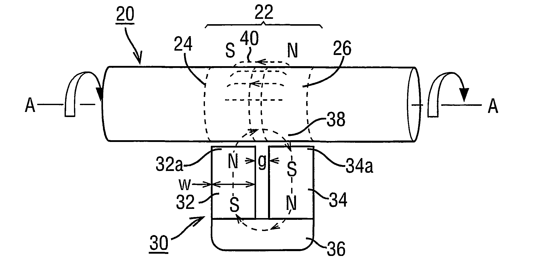
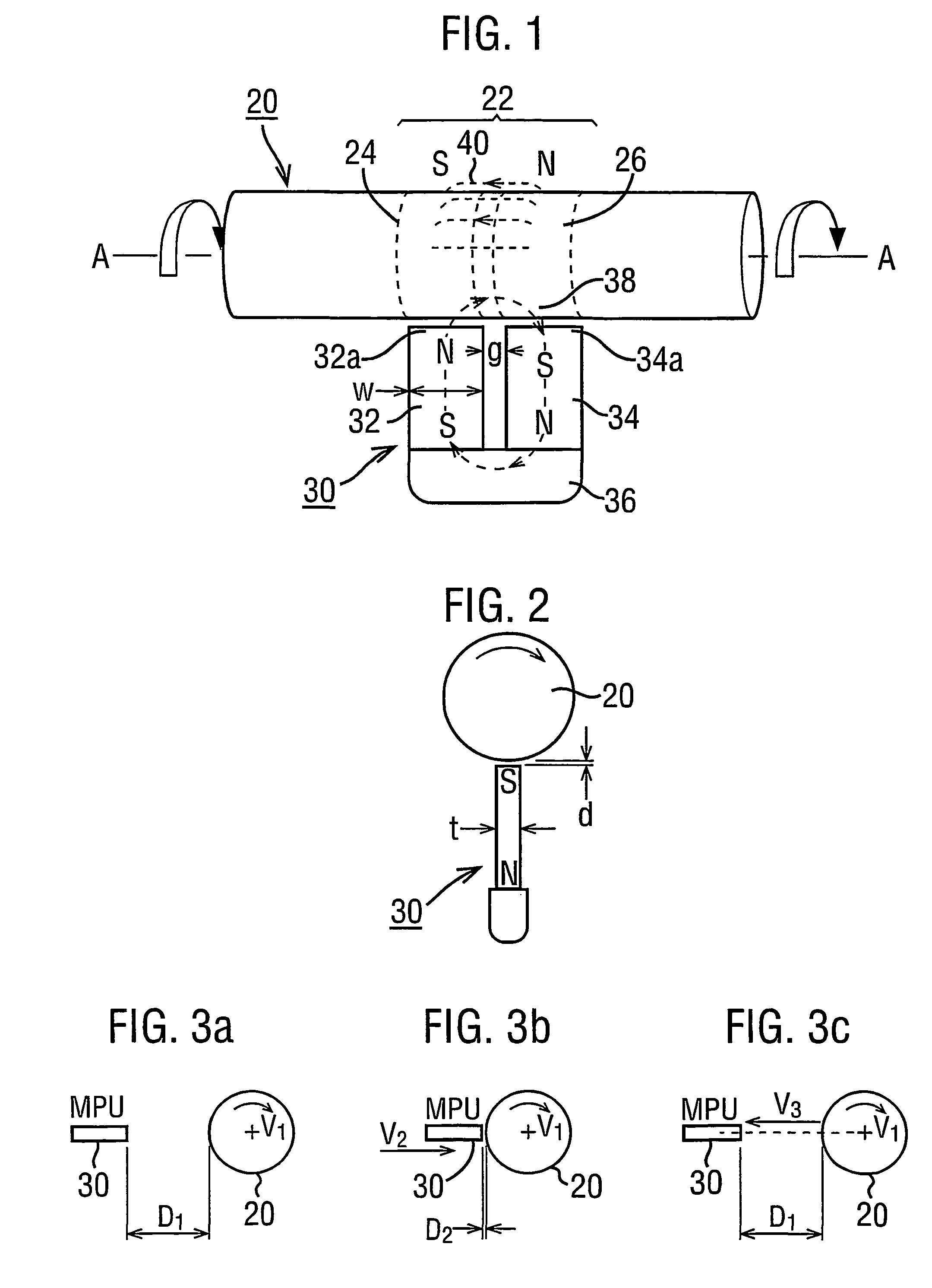
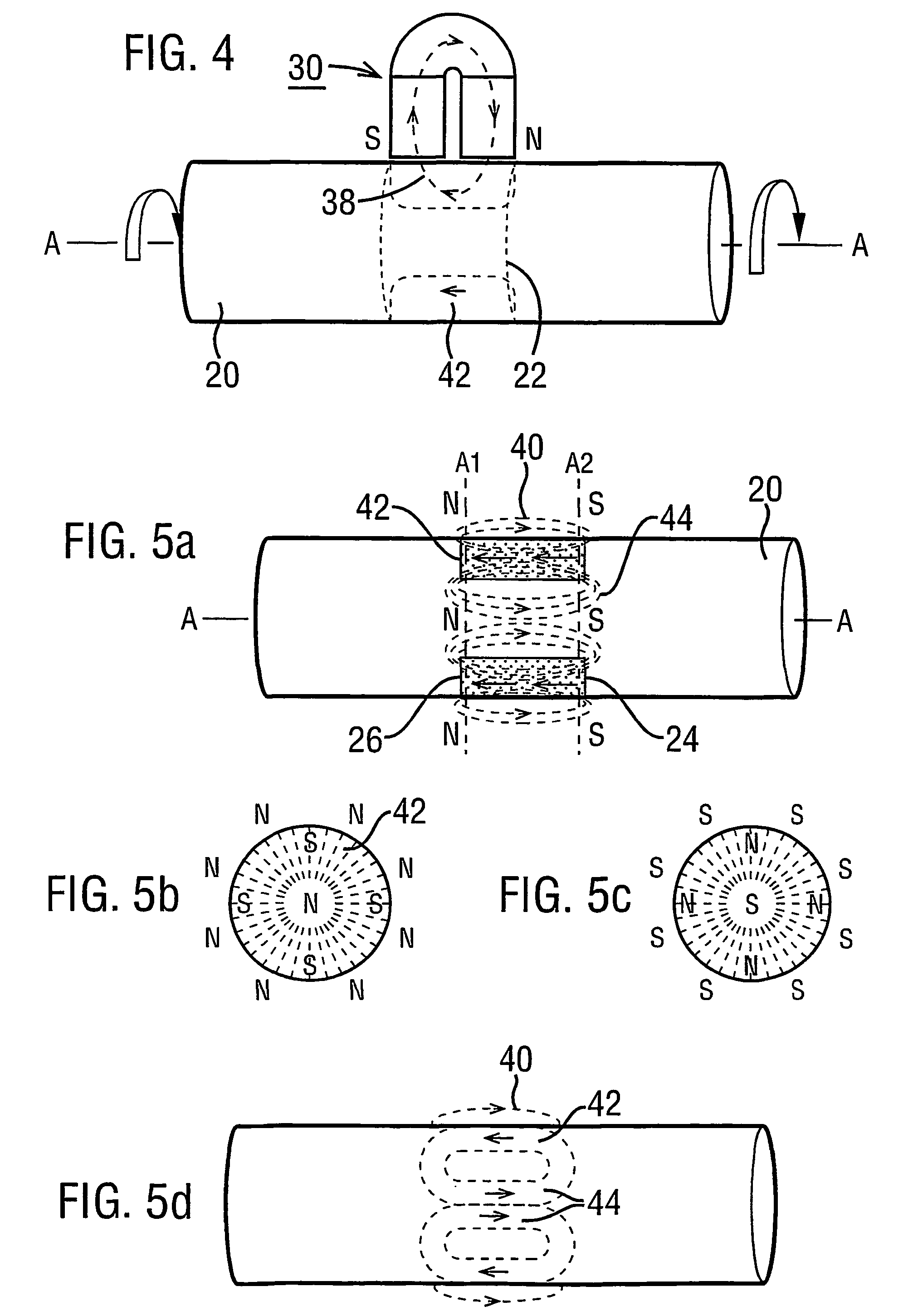
[0114]Reverting to the magnetisation of a region 22 such as described with reference to FIGS. 1–5, it has been explained in step 1) of the Magnetising Procedure described above, that the shaft should be rotated at a constant angular velocity V1.

[0115]The practical transducer use of the single region 22 is illustrated in FIG. 14 (with FIG. 7) and FIG. 15 (with FIG. 8) for axial and radial field profiles respectively. In each case the response of the profile to torque is the effect of axially shifting the profile. There is an additional factor which enters into these response curves. The direction of the axial shift with torque is dependent on the direction of rotation of the shaft while it is being magnetised. This is a most surprising result for which no physical explanation is presently available. However, it has been demonstrated in experiments and provides the basis of solving a problem which arises with a single transducer region 22.

[0116]The problem is the potential sensitivity...


PUM

PropertyMeasurementUnit
widthaaaaaaaaaa
voltagesaaaaaaaaaa
coil resistanceaaaaaaaaaa

Abstract

A magnetic transducer element (22) is formed by rotating an integral region of a shaft (20) about an axis (A—A) in the presence of a magnetic source (30). An annulus (42) of magnetisation results in having its magnetisation in the axial direction. The exterior magnetic field (40) emanated by the annulus (42) exhibits respective axial magnetic profiles of its axially and radially directed components (FIGS. 7 and 8) which have an axial shift under torque. The direction of profile shift depends on the rotational direction of the shaft (20) while magnetisation proceeds. A pair of regions (122a, 122b: 242, 244) exhibiting opposite shift directions provide signals in which torque-dependent shift is separated from axial displacements of the shaft (FIG. 22, FIG. 24). An annulus (42) of magnetisation may be non-uniform with angle about the shaft axis. Measures to prevent eddy currents generated in the rotating region of the shaft under magnetisation are disclosed as are “sweet spots” (230) for sensor placement (FIG. 30) to mitigate non-uniformity effects.

Description

[0001]This application is a 371 of PCT / EP01 / 06482.FIELD OF THE INVENTION[0002]This invention is concerned with the measurement of torque using a magnetic based transducer element assembly. The transducer element may also find application to the measurement forces generating bending moments acting on the element. More particularly, it is concerned with magnetic transducer elements which exhibit a form of torque-dependent magnetic field referred to herein as profile-shift longitudinal magnetisation. Such magnetisation is realised in a shaft, usually an integral portion of the shaft, as an annulus of magnetisation about the shaft axis which is in the direction of the shaft (extends longitudinally) and which emanates a detectable external field the profile of which takes in the direction of the axis shifts when torque is applied about the axis of the shaft.[0003]The present invention is particularly concerned with problems which arise due to movement of the shaft under torque in the dir...

Claims


Application Information

Patent Timeline
Patent Type & Authority Patents(United States)
IPC IPC(8): G01L3/02G01L3/10G01L3/12G01L3/14
CPCG01L3/101G01L3/109G01L3/104G01L3/105
Inventor MAY, LUTZ AXEL
Owner ABAS
Why Eureka
Try Eureka