Multivariable generator and method of using the same

a generator and multi-variable technology, applied in the direction of synchronous machines with stationary armatures and rotating magnets, electrical apparatus, acyclic motors, etc., can solve the problems of limited lifespan of rotors and/or stators, limited voltage and current generation ranges of generators, and significant heat and friction during operation of generators, so as to improve efficiency, reduce heat generation, and increase operation lifespan

Inactive Publication Date: 2006-04-27
MAGNETIC TORQUE INT
View PDF18 Cites 27 Cited by
  • Summary
  • Abstract
  • Description
  • Claims
  • Application Information

AI Technical Summary

Benefits of technology

[0014] Another object of the present invention is to provide a method of using a generator capable of having an increased operational lifespan.
[0015] Another object of the present invention is to provide a method of using a generator capable of reducing heat generation and improving efficiency.

Problems solved by technology

However, due to the specific configuration of the generator, only single phase and frequency may be produced by the generator.
Moreover, the specific configuration of the generator may only allow for generation of limited ranges of voltage and current.
Due to the specific relative configuration of the rotor and stator, significant amounts of heat and friction are created during operation of the generator.
Thus, the lifespan of the rotor and / or stator is limited by the ability to withstand elevated temperatures for extended periods of time.
Thus, the periodic maintenance is costly and time consuming.
Thus, the repeated changing of the magnetic moment of the cores generates heat, thereby reducing the strength of the cores, reducing the effective lifespan of the cores and limiting power output of the generator; all of which reduces efficiency.
This cogging effect significantly reduces efficiency of the generator and produces mechanical vibration throughout the generator.

Method used


Image

  • Multivariable generator and method of using the same
  • Multivariable generator and method of using the same
  • Multivariable generator and method of using the same

Examples


Embodiment Construction

[0034] Reference will now be made in detail to the preferred embodiments of the present invention, examples of which are illustrated in the accompanying drawings.

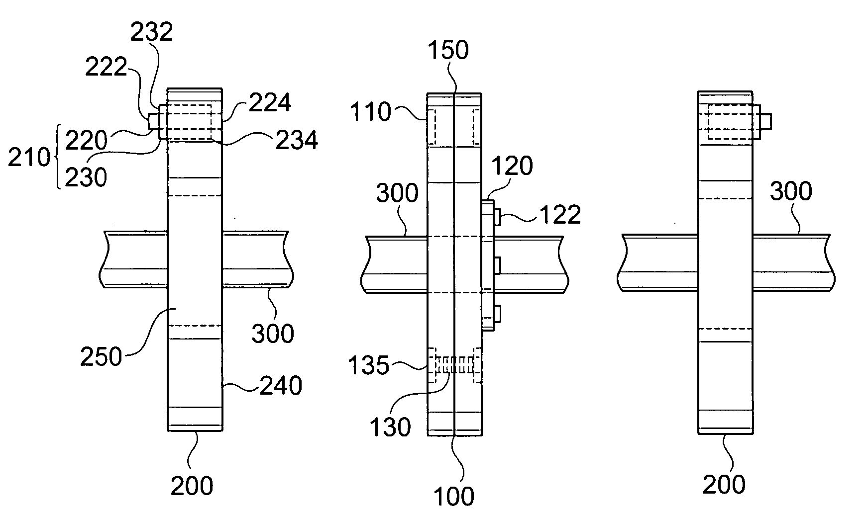
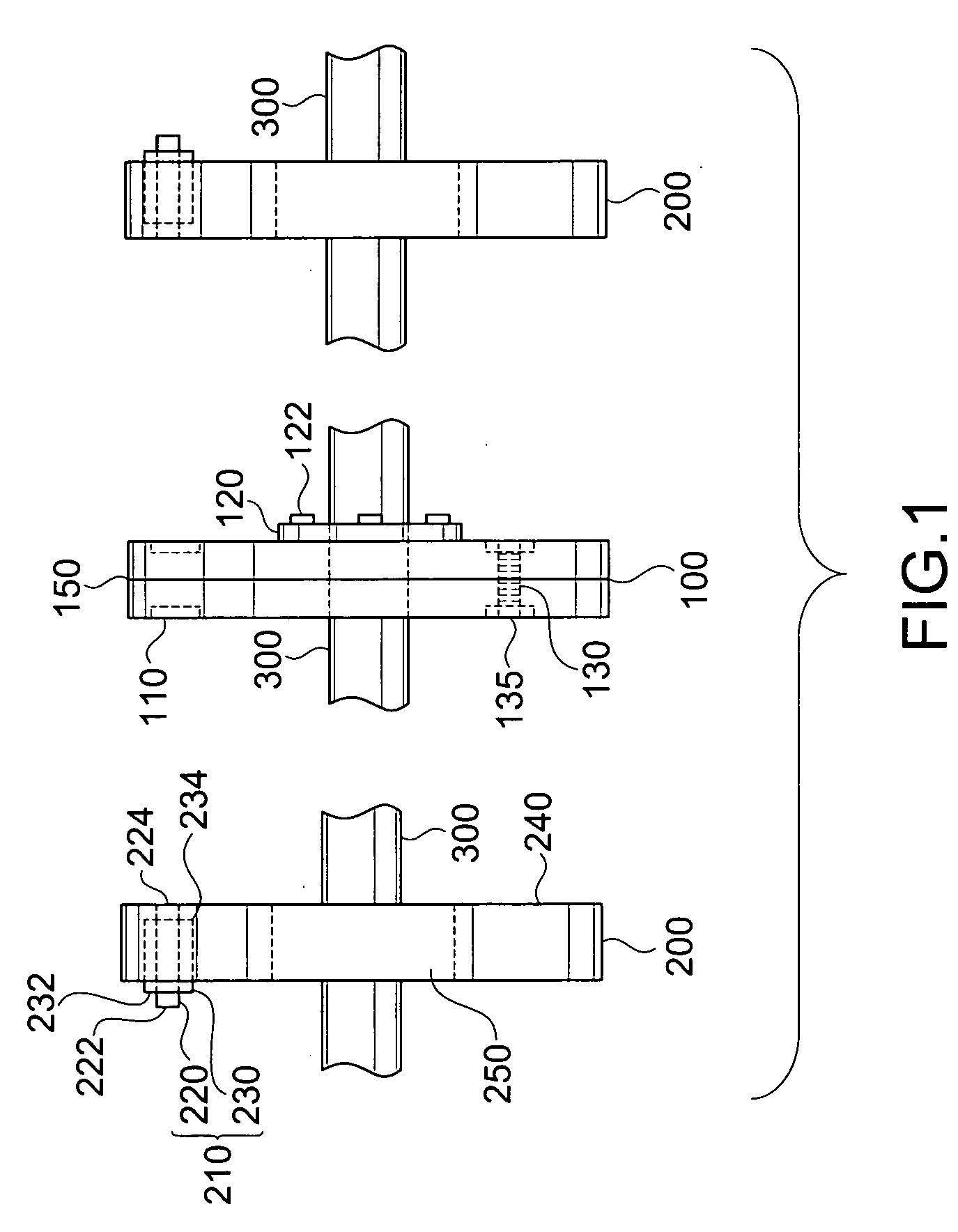
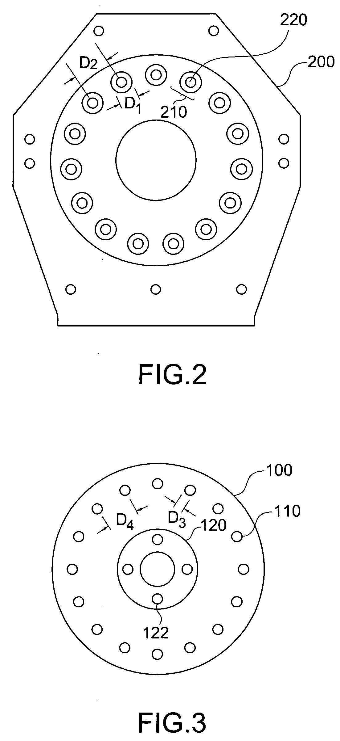
[0035]FIG. 1 is schematic side view of an exemplary multivariable generator according to the present invention. In FIG. 1, a generator may include a rotor 100 and a pair of stators 200 each disposed on opposing sides of the rotor 100. Each of the rotors 100 and the stators 200 may be made from non-magnetic materials. Alternatively, the generator may include a single rotor 100 and one stator 200 disposed at one side of the single rotor 100. The rotor 100 may include a plurality of magnetic sources 110 disposed through a thickness of the rotor 100, and the stator 200 may include a plurality of coil members 210 each disposed along a circumferential portion of the stator 200. For example, the stators 200 may include an “n”-number of the coil members 210, whereas the rotor 100 may include an “n+1”-number of the magnetic members...


PUM


Abstract

A generator device for generating electrical energy includes a rotor having an even number of magnetic sources, and a first pair of stators, each having an odd number of coil members, the stators disposed adjacent to opposing side portions of the rotor.

Description

BACKGROUND OF THE INVENTION [0001] 1. Field of the Invention [0002] The present invention relates to a generator and a method of using a generator, and particularly, to a multivariable generator and method of using a multivariable generator. [0003] 2. Discussion of the Related Art [0004] In general, electrical generators include at least one stator having a plurality of magnets and a rotor having a plurality of coil windings to generate electrical energy. Specifically, the rotor rotates along a first axis such that the coil windings are disposed along the first axis, and the stator is disposed adjacent to the rotor, wherein as the coil windings of the stator pass through a magnetic field created by the plurality of magnets of the rotor an electrical current is induced through the coil windings. [0005] However, due to the specific configuration of the generator, only single phase and frequency may be produced by the generator. Moreover, the specific configuration of the generator may...

Claims


Application Information

Patent Timeline
Patent Type & Authority Applications(United States)
IPC IPC(8): H02K21/12H02K31/00H02K39/00
CPCH02K21/24
Inventor WISE, RICHARD J.
Owner MAGNETIC TORQUE INT
Why Eureka
Try Eureka